background image

MACHINES AND
ACCESSORIES

Page 26 of 26

12 DIAGRAM OF THE ELECTRICAL CIRCUIT

fervi.com

Summary of Contents for 0560

Page 1: ...USE AND MAINTENANCE MANUAL Bench chamfering machine Art 0560 ORIGINAL INSTRUCTIONS fervi com ...

Page 2: ...l of the necessary information and instruction and should be provided with adequate training regarding safety in pertaining to a The conditions of use of the equipment b Foreseeable abnormal situations pursuant to art 73 of Legislative Decree no 81 08 We guarantee the machine complies with the specifications and technical instructions described in this Manual on the date of issuance listed on here...

Page 3: ...NSTALLATION 15 5 1 Connection of the electric power supply plug and start test 15 6 MAIN SWITCH AND CONTROL SWITCH 16 6 1 Main switch 16 6 2 Stop switch 16 7 OPERATION 17 7 1 Precautions for use 17 7 2 Before using the Bench chamfering machine 18 7 3 Use of the Bench chamfering machine 18 7 4 Adjusting the Bench chamfering machine 19 8 MACHINE SAFETY DEVICES 20 8 1 Electrical safety devices 20 8 2...

Page 4: ...r efficiency and safety in the workplace and the people considered suitable to perform a specific job must have the sufficient physical and mental capacity to allow them to understand the instructions that they are given 1 1 Graphic form of the alerts related to safety operation risk warnings The following boxes are designed to attract the attention of the reader user for the purposes of proper an...

Page 5: ...ns contained herein in addition to the general precautions to be observed while working Acquire full knowledge of the machine Read this manual carefully to learn about operation safety devices and all necessary precautions All of this allows safe use of the machine Wear appropriate clothing for the job The operator must wear appropriate clothing to prevent the occurrence of unpleasant accidents Ta...

Page 6: ...g any work on the machine the operator must wear the appropriate personal protective equipment PPE such as goggles gloves and non slip shoes Qualifications of the operator The operators assigned to using this machine must have all the necessary information and instruction and should be given adequate training in relation to safety regarding a the conditions of use of the equipment b foreseeable ab...

Page 7: ...er moving parts have completely stopped 17 Replace worn and or damaged parts check that the guards and protection devices work correctly before operating You may if necessary have the machine checked by the service support personnel Use only original spare parts 18 Unplug the power cord of the machine from the power outlet when not using the machine it is left unattended performing maintenance or ...

Page 8: ... grounded 10 16 A 250 V any extension cords must have the same or greater cross sections than those of the machine s power cord 4 Ensure that the power cord does not come into contact with hot objects surfaces that are wet oily and or have sharp edges 5 The power cable must be checked regularly and before each use to check for signs of damage or wear If not in a good condition do not use the machi...

Page 9: ... W 250 Voltage V 230 Frequency Hz 50 Rotation speed rpm 2 800 Mill size mm 80 Chamfering capacity 45 mm 5 Weight kg 25 Chamfer angle 45 Material input angle 90 Guide width mm 50 Guide length mm 400 Noise level dB 65 Motor data Type Single phase asynchronous Class B Degree of protection IP 44 fervi com ...

Page 10: ...ided with two steel sliding planes which are perpendicular to each other and inclined at 45 with respect to the vertical plane The milling cutter is almost entirely covered by the guide itself which therefore acts as a protective guard The machine is able to perform a maximum chamfer of 5 mm The start and stop are controlled with two buttons located on the upper part of the electrical panel In the...

Page 11: ...ge 11 of 26 4 1 Description of the main parts Side view piece input side Side view piece guide side Tool detail Group of diagrams 1 Main parts of the bench chamfering machine 10 8 7 6 5 11 3 4 1 2 2 11 10 9 12 13 14 15 fervi com ...

Page 12: ...cking knob 0560 02 Guide rail 0560 07 Power switch 0560 12 Insert locking screw 0560 03 Electrical panel 0560 08 Locking micro switch 0560 13 Milling cutter 0560 04 Power cord 0560 09 Drawer knob 0560 14 Wedge 0560 05 Main switch 0560 10 Chamfer adjustment screw 0560 15 Cutting insert fervi com ...

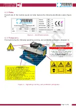
Page 13: ...ROTECTIVE EQUIPMENT SUCH AS GOGGLES AND MASKS IF POWDER IS PRODUCED DISCONNECT THE MACHINE FROM THE POWER SUPPLY IN THE EVENT OF REPAIRS OR ADJUSTMENTS BEING MADE DO NOT WEAR LOOSE CLOTHING JEWELLERY CHAINS AND BRACELETS WHICH CAN CATCH ON THE MOVING PARTS CAUSING IRREPARABLE INJURY DISCONNECT THE MACHINE FROM THE POWER SUPPLY BEFORE PERFORMING MAINTENANCE REPAIRS AND ADJUSTMENTS WARNING DO NOT CA...

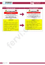
Page 14: ...MOVIMENTO NON AFFERRARE IL PEZZO CON LE MANI PER ARRESTARLO NON REGOLARE LA MACCHINA MENTRE È IN FUNZIONE INDOSSARE SEMPRE IDONEE PROTEZIONI QUALI OCCHIALI E MASCHERINE QUALORA VENFA PRODOTTA POLVERE SCOLLEGARE LA MACCHINA DALL ALIMENTAZIONE ELETTRICA IN CASO DI RIPARAZIONI O REGOLAZIONI NON INDOSSARE INDUMENTI SVOLAZZANTI GIOIELLI CATENINE E BRACCIALI CHE POSSONO AGGANCIARSI ALLA MACCHINA E CAUSA...

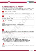
Page 15: ...ce vibration e g rubber between the Chamfering machine and the supporting surface Installation of the machine Do not install the machine outdoors to avoid deformation loss of functionality and damage to the electrical control circuit 5 1 Connection of the electric power supply plug and start test 1 Insert the power supply plug into a grounded double pole socket 10 16 A 250 V 2 Turn the main switch...

Page 16: ...ting switching on the Chamfering machine By pressing this button the electric motor is powered and the tool milling cutter is put into rotation Figure 5 Control switches 6 3 Stop switch The red STOP button ref A in Figure 5 is used for shutting down the Bench chamfering machine both under normal conditions of use and in cases of emergency By pressing this button power to the electric motor is swit...

Page 17: ...ropriate personal protective equipment PPE such as gloves goggles overalls or aprons and safety shoes It is not recommended to extend the continued use of the machine for more than 10 minutes to avoid overheating of the machine which could damage the motor and the tool NOTE The Bench chamfering machine can not operate in environments with potentially explosive atmospheres It is therefore the respo...

Page 18: ... accident Hold the piece at the upper and rear part DO NOT place fingers under the work piece for any reason NEVER grab the work piece with bare hands it has a high temperature and sharp burrs Always wear appropriate personal protective equipment PPE such as gloves to avoid injury Thin or small pieces When working with very thin or small pieces a special tool must be used to push the piece and hol...

Page 19: ...b ref 11 in figure 6 2 rotate the adjustment screw ref 10 until the inserts of the milling cutter touch the workpiece 3 turn the screw until it reaches the desired depth each turn corresponds to approximately 0 5 mm 4 once the depth of the chamfer has been determined lock the locking knob ref 11 Figure 6 Adjustment commands Adjustment of the Chamfering machine Any adjustments must be performed wit...

Page 20: ...d and plug with a grounding conductor that provides a path of least resistance for the electric current by reducing the danger of electrocution The plug must be inserted into a suitable socket grounded in accordance with regulations in force Any extension cords must have the same or greater cross sections than those of the machine s power cord Electric shock Improper connection of the grounding co...

Page 21: ...e to be performed on the machine Checking Safety devices Each time the Bench chamfering machine is used check the perfect functioning and positioning of the safety devices Do not use the machine in the case of damage and or breakage Use of PPE In any event ALWAYS use appropriate personal protective equipment PPE such as Gloves Goggles or face shields Overalls or apron Safety shoes PROTECTIVE GLOVE...

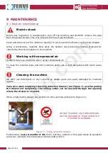
Page 22: ...r To clean the machine body and other external parts use a cloth dampened with warm water only Cleaning the machine DO NOT use detergents or any solvents as plastic parts are easily damaged by chemical agents Take care when emptying the filing collection drawer see Figure 7 as after pulling the drawer out completely the milling cutter can be reached through the opening where the drawer is inserted...

Page 23: ...ure 12 and perform the following steps 1 unscrew the inserts locking screw ref 12 2 extract the cutting insert ref 15 3 replace it with the new insert 4 position the locking wedge ref 14 and tighten the locking screw again ref 12 Continue in this way for all the cutting inserts to be replaced Figure 8 Replacement of cutting inserts 10 DISPOSAL OF COMPONENTS AND MATERIALS If the machine is to be sc...

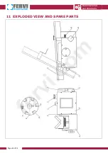
Page 24: ...MACHINES AND ACCESSORIES Page 24 of 26 11 EXPLODED VIEW AND SPARE PARTS fervi com ...

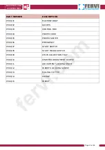
Page 25: ...3 CONTROL BOX 0560 04 POWER CORD 0560 05 POWER SWITCH 0560 06 EMERGENCY 0560 07 START SWITCH 0560 08 START MICRO SWITCH 0560 09 CHIPS COLLECTION TRAY 0560 10 CHAMFER ADJUSTMENT SCREW 0560 11 ADJUSTMENT LOCKING KNOB 0560 12 INSERTS LOCKING SCREW 0560 13 MILLING CUTTER 0560 14 WEDGE 0560 15 INSERT fervi com ...

Page 26: ...MACHINES AND ACCESSORIES Page 26 of 26 12 DIAGRAM OF THE ELECTRICAL CIRCUIT fervi com ...

Reviews: