MACHINES AND
ACCESSORIES
Page 34 of 41
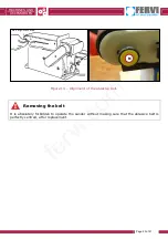
Figure 22 – Move the belt into a vertical position.
6. Mount the work table onto the vertical belt, inserting the pin (D) and the lever (E) in
the auxiliary holes present on the side of the belt-holder frame, as shown in figure 24.
Figure 23 - Worktable assembly.
7. Tighten the working table locking lever (E), turning it clockwise.
Allen
screw
Table
locking
lever
Table
support
Auxiliary
assembly
holes
Washer
Pulley
guard
fervi.com


