background image

HARDWARE

Page 11 of 13

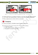
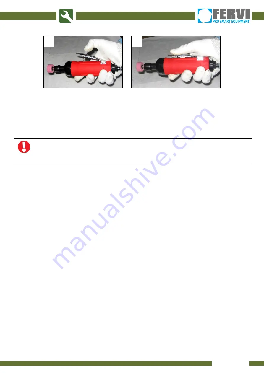
Figure 7 – Turning on the grinder (A: disabling the safety – B: press the lever).

The grinder's start lever is a continuous hold lever, in the sense that the function controlled

(i.e., the rotation of the grinding wheel) is active as long as the lever itself is kept pressed.

Therefore, release the lever to shut it down in an emergency.

Emergency

In case of an emergency, immediately release the grinder's power lever.

Disconnect the air hose and turn off the tool in the event of the following:

to replace the wheels;

to clean, rebuild or perform maintenance on the grinder;

if the grinder is not used for some time.

A

B

fervi.com

Summary of Contents for 570

Page 1: ...USER AND MAINTENANCE MANUAL Axial Grinder Set with Sanding Attachments Art 0570 TRANSLATION OF THE ORIGINAL INSTRUCTIONS fervi com ...

Page 2: ...ng this machine must have all necessary information education and receive adequate training regarding safety including a Conditions of use for the equipment b Foreseeable abnormal situations pursuant to art 73 of Legislative Decree no 81 08 We guarantee the Machine s conformity to specifications and technical instructions described in the Manual on the date of issue listed on this page however the...

Page 3: ...ts 4 1 3 Personal Protective Equipment 4 1 4 Technical Support 4 2 DESCRIPTION OF THE GRINDER AND INTENDED USE 5 2 1 Technical Specifications 5 2 2 Identification Plate 6 3 IMPROPER USES AND PRECAUTIONS 6 4 COMMISSIONING 7 5 HOW TO USE 8 5 1 Attaching the Abrasive Tools 8 5 2 Power On Off 10 6 MAINTENANCE AND CLEANING 12 7 BILL OF MATERIALS AND SPARE PARTS 13 fervi com ...

Page 4: ...hile working Beware of air hoses which can cause you to trip and fall 1 2 Risks Associated with the Presence of Rotating and or Moving Parts 1 Grab the pneumatic tool correctly using the appropriate torch handle 2 Never touch the rotating parts of the tool particularly the ratchet bearing 3 Vibration repetitive motions and uncomfortable positions may be harmful to your arms and hands Discontinue u...

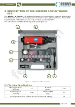
Page 5: ...ive tools grinding wheels it is possible to grind or polish different materials such as metals wood and plastic The kit is made up of the following parts see Figure 1 Figure 1 Overview of the machine 2 1 Technical Specifications Working pressure kPa bar 6 Air intake l min 150 Rotation speed rev min 2100 Empty weight kg 1 3 Sound pressure level emitted into the environment dB A 79 1 2 3 4 5 8 6 7 f...

Page 6: ...ng Use the tool in humid conditions explosive atmospheres or near flammable surfaces or gases Use the tool without wearing appropriate PPE such as footwear gloves hearing protectors and goggles Touch rotating parts during operation Use the tool in the presence of children Leave the compressed air supply hose inserted after work or while changing the grinding wheel Point the grinder in the directio...

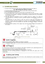
Page 7: ...ies 3 to 6 drops of oil per minute Furthermore the maximum length of the hose between the lubricator and the tool must be a maximum of 6 8 meters 8 Insert the quick coupling of the supply hose into the air inlet nozzle at the bottom of the handle Figure 3 Connecting the air supply Quick Coupling Always ensure that the quick coupling is perfectly connected Make sure that the outer ring of the quick...

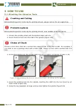
Page 8: ...he grinder Figure 4 A Choice of Chuck Choose a tool chuck that has a central hole equal to that of the tool s shaft For example if you want to use a grinding wheel with a 6mm shaft choose a chuck with a central hole of 6 mm 3 Screw the spindle onto the grinder shaft but do not tighten completely Figure 4 B Figure 4 Assembling the tool A insert the chuck B screw on the spindle 4 Insert the grinding...

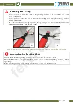
Page 9: ...rrectly tightened the grinding wheel may suddenly release and may hit the operator in the face or chest Figure 5 Assembling the tool A assembled grinding wheel B tightening the spindle Assembling the Grinding Wheel Always check that the grinding wheel is compatible with the pneumatic tool Check that the wheel is in good condition i e no cracks and not completely worn out before operating Make sure...

Page 10: ...therefore avoid the presence of flames or hot surfaces in the work area After assembling the grinding wheel and connecting the flexible compressed air supply hose grab the grinder by its torch handle The Grinder Art 0570 is equipped with a screw for adjusting the grinding wheel s rotation speed according to the type of material the harder the material the greater the speed of rotation Turn the gri...

Page 11: ...grinding wheel is active as long as the lever itself is kept pressed Therefore release the lever to shut it down in an emergency Emergency In case of an emergency immediately release the grinder s power lever Disconnect the air hose and turn off the tool in the event of the following to replace the wheels to clean rebuild or perform maintenance on the grinder if the grinder is not used for some ti...

Page 12: ...sary to rid the body of oil deposits dust or dirt accumulation Risks Associated with Cleaning Disconnect the air supply hose and clean the body of the tool Do not use organic solvents to avoid corrosion or discolouration 3 Clean the air outlet nozzle cleaning is necessary to free the hot air outlet nozzle and dirt accumulation filter Do not use paint thinner gasoline or similar substances to clean...

Page 13: ...1 Cylinder 0570 06 Air valve bushing 0570 22 Conical muffler 0570 07 Air valve 0570 23 Bearing spacer 0570 08 O ring 0570 24 Front closure 0570 09 Air connector 0570 25 Bearing 0570 10 Outlet sleeve 0570 26 Washer 0570 11 O ring 0570 27 Lock nut 0570 12 Rubber pin 0570 28 Spindle 0570 13 Operating lever 0570 29 Intake 0570 14 Rubber grip 0570 30 Intake nut 0570 15 Casing 0570 31 14mm hex wrench 05...

Reviews: