4. Commissioning
4-16
Festo P.BE-MPA-EN en 1108e
MPA-S valve terminal with CPX terminal or
CPI module
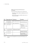
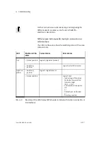
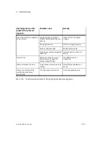
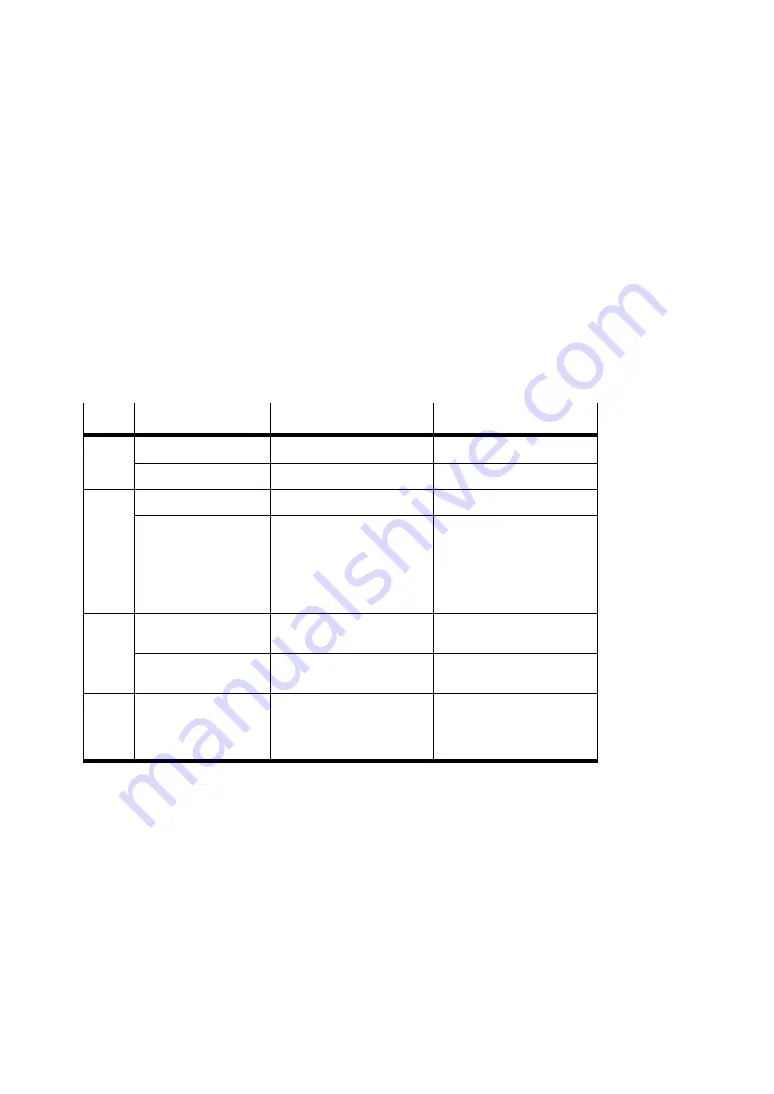
The two-colour LEDs on the valves have a double function.
–
When yellow, the LEDs indicate the switching status of the
solenoid coils.
–
When red during operation, the LEDs indicate an error in
the electronic module.
LED
Position of the valve
Correct state
Error status
Out
– Normal position
Logical 0 (signal not present)
– Switching position
Logical 0 after MO actuated
Yellow
illumi-
nated
– Switching position
Logical 1 (signal present)
– Normal position
Logical 1 but:
– the compressed air supply
is not OK or
– the pilot exhaust is blocked
or
– Servicing required
Red
illumi-
nated
– in the starting phase
for approx. 2 seconds
Check phase when the supply
voltage has been switched on
– during operation
See electronics description of
the MPA pneumatic module
Red
fla-
shing
– during operation
MPA-S with electronics module
VMPA...-FB-EM...-
D2
...:
See electronics description of
the MPA pneumatic module
Tab. 4/6:
Meaning of the LED display (MPA-S valve terminal with CPX terminal or CPI
module)
Summary of Contents for 530411
Page 2: ......
Page 4: ...Contents and general instructions II Festo P BE MPA EN en 1108e ...
Page 16: ...Contents and general instructions XIV Festo P BE MPA EN en 1108e ...
Page 17: ...Summary of components 1 1 Festo P BE MPA EN en 1108e Chapter 1 Summary of components ...
Page 59: ...Fitting 2 1 Festo P BE MPA EN en 1108e Chapter 2 Fitting ...
Page 73: ...Installation 3 1 Festo P BE MPA EN en 1108e Chapter 3 Installation ...
Page 108: ...3 Installation 3 36 Festo P BE MPA EN en 1108e ...
Page 109: ...Commissioning 4 1 Festo P BE MPA EN en 1108e Chapter 4 Commissioning ...
Page 172: ...5 Maintenance and conversion 5 42 Festo P BE MPA EN en 1108e ...
Page 173: ...Technical appendix A 1 Festo P BE MPA EN en 1108e Appendix A Technical appendix ...
Page 209: ...Index C 1 Festo P BE MPA EN en 1108e Appendix C Index ...
Page 210: ...C Index C 2 Festo P BE MPA EN en 1108e Contents C Index C 1 ...


