5. Maintenance and conversion
5-33
Festo P.BE-MPA-EN en 1108e
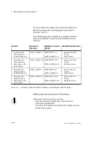
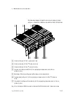
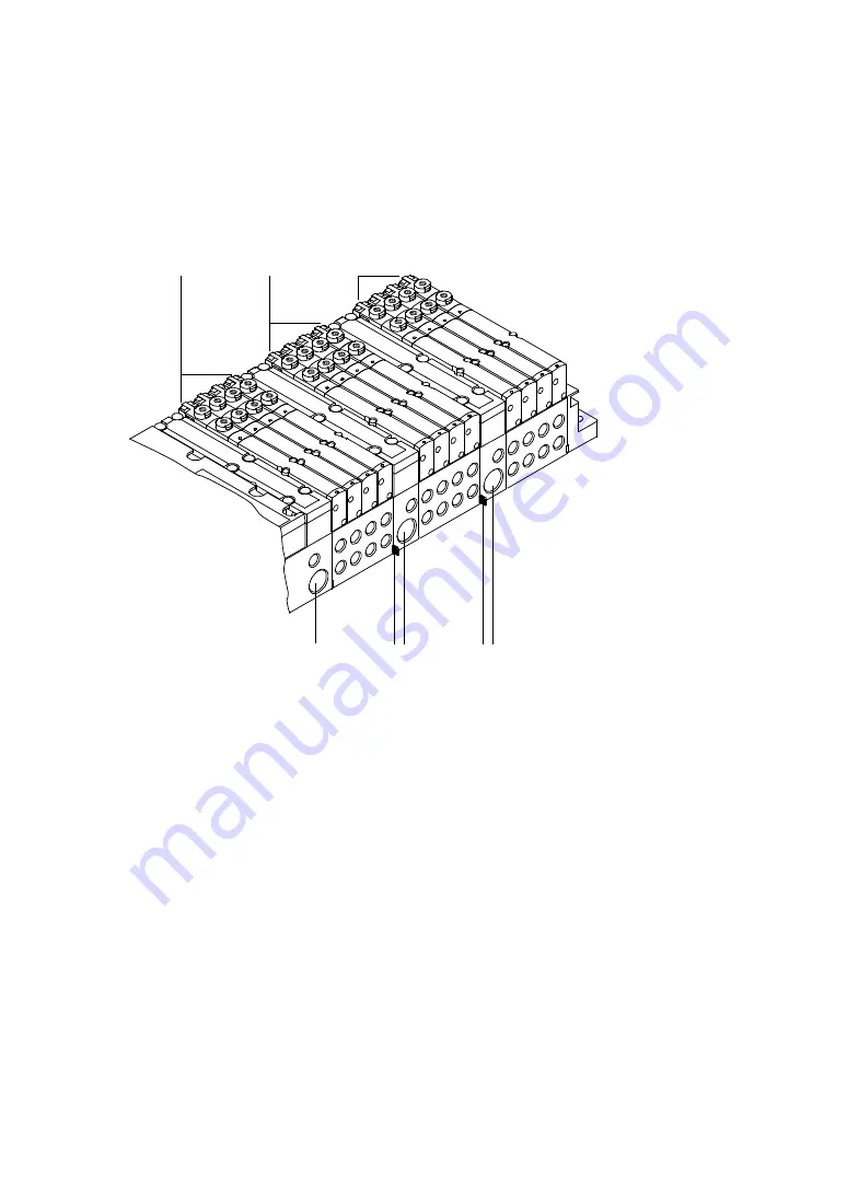
The following diagram shows the structure of pressure zones
using as an example an MPA-S valve terminal with CPX terminal.
1
2
3
4
5
6
7
5
1
Valve sub-bases of the 1
st
pressure zone
2
Valve sub-bases of the 2
nd
pressure zone
3
Valve sub-bases of the 3
rd
pressure zone
4
Supply unit with connection (1) for supplying compressed air to the 3
rd
pressure zone
5
Marking of the separating seal with pressure zone separation
6
Supply plate with port (1) for supplying compressed air to the 2
nd
pressure
zone
7
Pneumatic interface with connection (1) for supplying compressed air to the 1
st
pressure zone
Fig. 5/16: Example of MPA-S valve terminal with CPX terminal and 3 pressure zones
Summary of Contents for 530411
Page 2: ......
Page 4: ...Contents and general instructions II Festo P BE MPA EN en 1108e ...
Page 16: ...Contents and general instructions XIV Festo P BE MPA EN en 1108e ...
Page 17: ...Summary of components 1 1 Festo P BE MPA EN en 1108e Chapter 1 Summary of components ...
Page 59: ...Fitting 2 1 Festo P BE MPA EN en 1108e Chapter 2 Fitting ...
Page 73: ...Installation 3 1 Festo P BE MPA EN en 1108e Chapter 3 Installation ...
Page 108: ...3 Installation 3 36 Festo P BE MPA EN en 1108e ...
Page 109: ...Commissioning 4 1 Festo P BE MPA EN en 1108e Chapter 4 Commissioning ...
Page 172: ...5 Maintenance and conversion 5 42 Festo P BE MPA EN en 1108e ...
Page 173: ...Technical appendix A 1 Festo P BE MPA EN en 1108e Appendix A Technical appendix ...
Page 209: ...Index C 1 Festo P BE MPA EN en 1108e Appendix C Index ...
Page 210: ...C Index C 2 Festo P BE MPA EN en 1108e Contents C Index C 1 ...

