2. Fitting
2-9
Festo P.BE-MPA-EN en 1108e
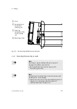
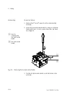
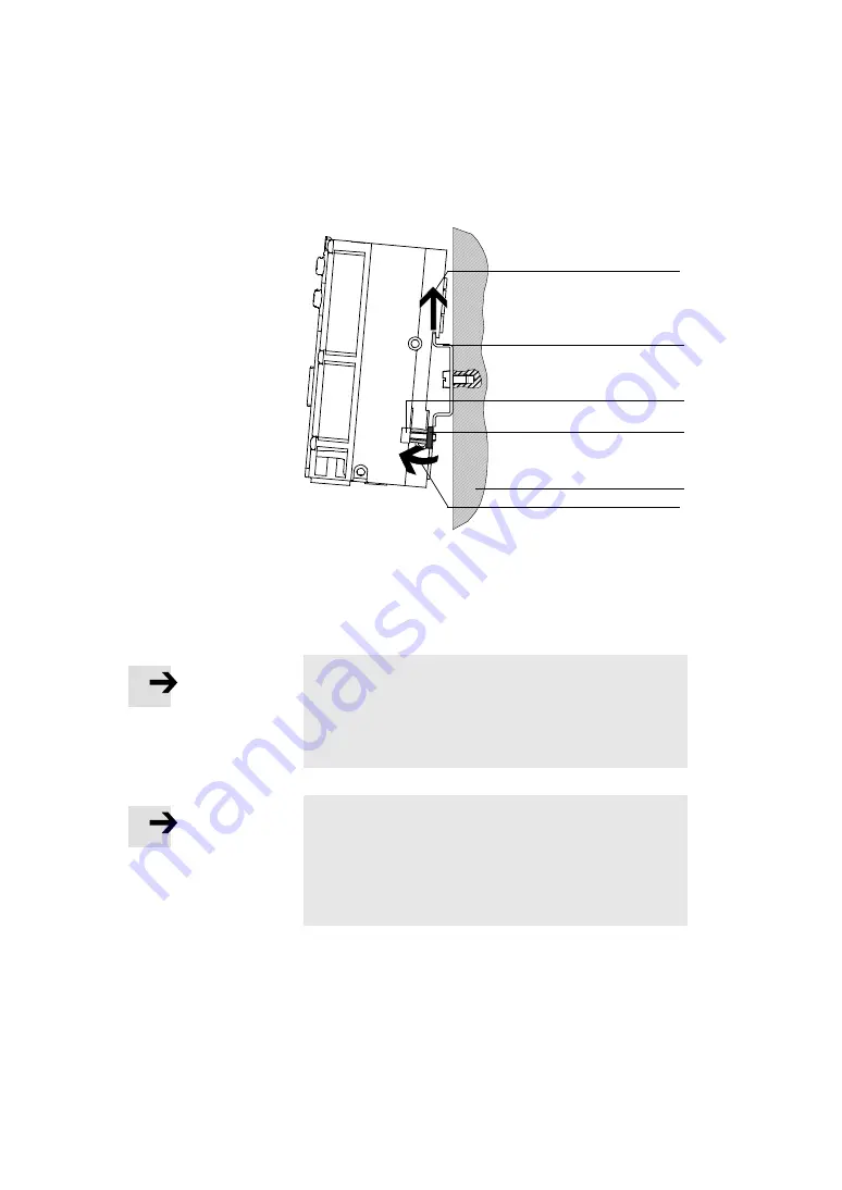
1
H-rail
2
Retaining screw
of the H-rail
clamping unit
3
Clamping
component of the
H-rail clamping
unit
4
Mounting surface
1
A
B
2
3
4
Fig. 2/3:
Dismounting the MPA-S valve terminal
2.2.2
Mounting/dismounting on walls
Note
Mounting on uneven, flexible surfaces can result in
damage to the MPA-S valve terminal.
•
Mount the MPA-S valve terminal only on a flat,
torsionally rigid surface.
Note
Overloading of mounting holes or natural resonance with
oscillations can cause damage.
•
Besides the instructions on standard fastening points in
Chapter 2.2.3, also observe the instructions on
additional fastening in Chapter 2.2.4.
Summary of Contents for 530411
Page 2: ......
Page 4: ...Contents and general instructions II Festo P BE MPA EN en 1108e ...
Page 16: ...Contents and general instructions XIV Festo P BE MPA EN en 1108e ...
Page 17: ...Summary of components 1 1 Festo P BE MPA EN en 1108e Chapter 1 Summary of components ...
Page 59: ...Fitting 2 1 Festo P BE MPA EN en 1108e Chapter 2 Fitting ...
Page 73: ...Installation 3 1 Festo P BE MPA EN en 1108e Chapter 3 Installation ...
Page 108: ...3 Installation 3 36 Festo P BE MPA EN en 1108e ...
Page 109: ...Commissioning 4 1 Festo P BE MPA EN en 1108e Chapter 4 Commissioning ...
Page 172: ...5 Maintenance and conversion 5 42 Festo P BE MPA EN en 1108e ...
Page 173: ...Technical appendix A 1 Festo P BE MPA EN en 1108e Appendix A Technical appendix ...
Page 209: ...Index C 1 Festo P BE MPA EN en 1108e Appendix C Index ...
Page 210: ...C Index C 2 Festo P BE MPA EN en 1108e Contents C Index C 1 ...


