3. Installation
3-11
Festo P.BE-MPA-EN en 1108e
By fitting an additional pneumatic air supply plate within a
pressure zone you can feed additional supply air or extract
exhaust air.
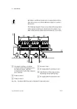
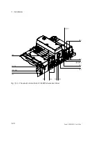
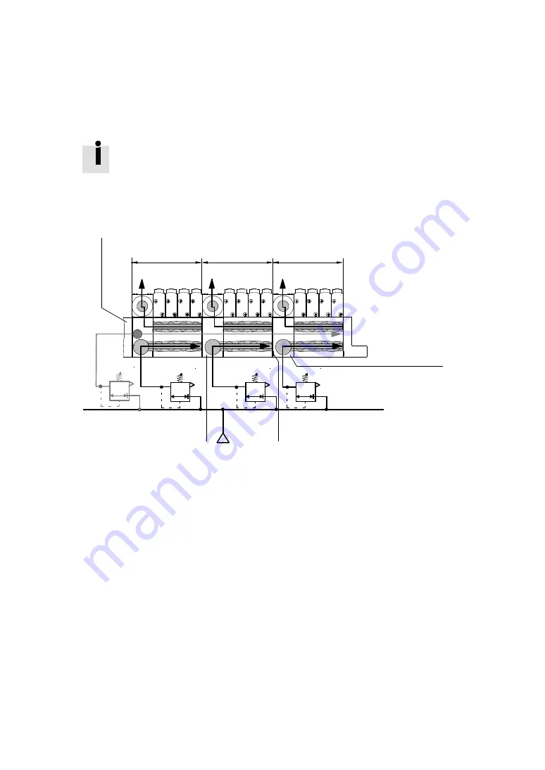
The following diagram shows as an example the assignment
of the supply and exhaust connections to the valves on an
MPA-S valve terminal with blocked channels (1), (3) and (5).
1
2
3
4
5
6
7
(12/14)
(1)
(1)
(1)
(3/5)
(3/5)
(3/5)
1
Pneumatic interface or multiple
connector plate with supply port (1)
for pressure zone 1 and pilot
connection (12/14) for the complete
valve terminal
2
Pressure zone 1
3
Pressure zone 2
4
Pressure zone 3
5
Air supply plate for pressure zone 3
6
Identification of the pressure zone
separating seal (projecting flag)
7
Air supply plate for pressure zone 2
Fig. 3/6:
Example of MPA-S valve terminal with 3 pressure zones
Summary of Contents for 530411
Page 2: ......
Page 4: ...Contents and general instructions II Festo P BE MPA EN en 1108e ...
Page 16: ...Contents and general instructions XIV Festo P BE MPA EN en 1108e ...
Page 17: ...Summary of components 1 1 Festo P BE MPA EN en 1108e Chapter 1 Summary of components ...
Page 59: ...Fitting 2 1 Festo P BE MPA EN en 1108e Chapter 2 Fitting ...
Page 73: ...Installation 3 1 Festo P BE MPA EN en 1108e Chapter 3 Installation ...
Page 108: ...3 Installation 3 36 Festo P BE MPA EN en 1108e ...
Page 109: ...Commissioning 4 1 Festo P BE MPA EN en 1108e Chapter 4 Commissioning ...
Page 172: ...5 Maintenance and conversion 5 42 Festo P BE MPA EN en 1108e ...
Page 173: ...Technical appendix A 1 Festo P BE MPA EN en 1108e Appendix A Technical appendix ...
Page 209: ...Index C 1 Festo P BE MPA EN en 1108e Appendix C Index ...
Page 210: ...C Index C 2 Festo P BE MPA EN en 1108e Contents C Index C 1 ...

