Job Sheet 3 – Variable-Speed Belt Drives
46
© Festo Didactic 54977-3C
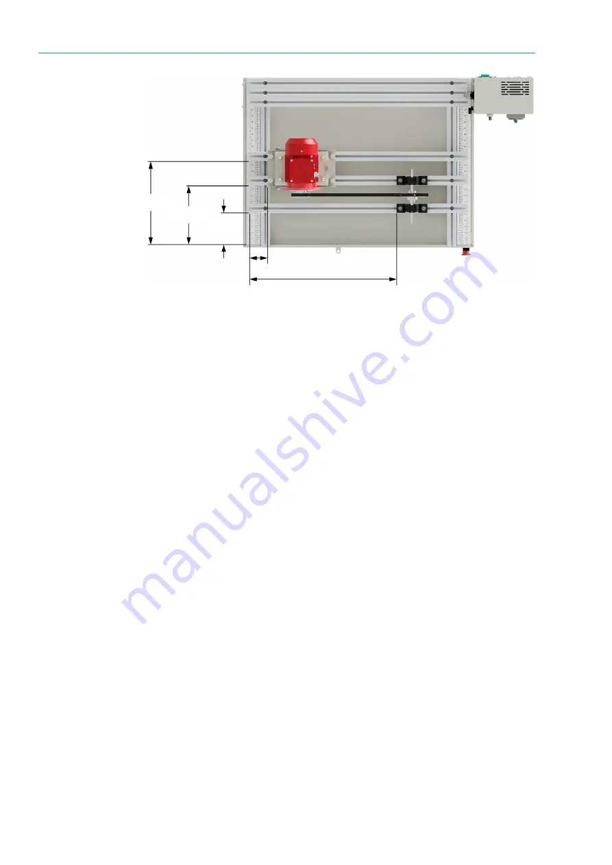
Figure 37. First workstation setup for Job Sheet 3.
3.
Install the motor mounting base on the extrusion bars, as shown in
Figure 37. Then tighten the screws following a crisscross pattern.
a
It is important that the mounting base level knob is located at your right for
proper adjustment of the position and tension.
4.
Fix the motor on the mounting base and then tighten the motor screws
following a crisscross pattern.
5.
Check for motor soft-foot before proceeding further. Apply the corrections if
necessary.
Pulleys installation
You will install the pulleys and set the variable-pitch pulley to the closed position.
6.
Install a key in the keyseat of the motor shaft. Align the key with the end of
the motor shaft.
7.
Take the 80 mm nominal diameter pulley and slide it on the motor shaft. The
pulley hub should be on the motor side. Make sure the end of the pulley is
aligned with the key on the motor shaft.
a
From now on, the 80 mm nominal diameter pulley will be referred to as the
driving pulley.
8.
Tighten the pulley setscrew on the shaft key.
a
Do not overtighten the pulley setscrew.
7.5 cm
60.7 cm
13 cm
24.5 cm
34.5 cm
Summary of Contents for Belt Drives 2
Page 1: ...Industrial Maintenance Belt Drives 2 Course Sample 54977 3C ...
Page 6: ......
Page 10: ......
Page 12: ......
Page 13: ...Sample Extracted from Job Sheets Instructor ...
Page 14: ......
Page 22: ......


