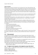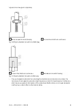
Plug
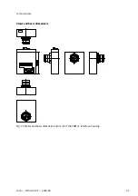
1
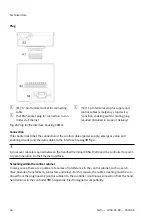
(K1) 17-pin Hummel socket for connecting
cable
2
(S2) RJ45 socket plug for connection to con-
troller via Ethernet
3
(S3) 11-pin terminal strip for supply and
control cables (emergency stop device,
3-position enabling switch), mating plug
required (included in scope of delivery)
Fig. 26 Plug for the interface housing CAMI-C
Connection
This chapter describes the connection of the control cables (power supply, emergency stop and
enabling circuits) and the data cables to the interface housing
è
A crossover cable is required between the handheld terminal CDSA-D3-RV and the controller for point-
to-point operation via the Ethernet interface.
Screening within the control cabinet
In many cases, there are a number of sources of interference in the control cabinet, such as servo
drive modules, transformers, contactors and relays. For this reason, the cable screening must be con-
tinued from the plug housing (control cabinet) to the controller (continuous connection from the hand-
held terminal to the controller
è
15 Appendix: Electromagnetic compatibility.
Technical data
46
Festo — CDSA-D3-RV — 2020-08

