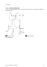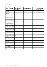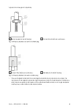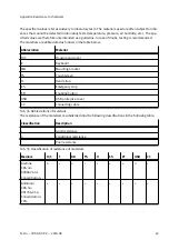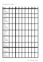
Signal description
S2, 12-pin socket
connector
S3, 8-pin RJ45 plug
S1, 17-pin plug con-
nector, pin no.
24 V DC
1
–
→
1
GND_IN
2
–
→
2
Emergency stop, cir-
cuit 2
3
–
→
3
Emergency stop, cir-
cuit 2
4
–
→
4
Emergency stop, cir-
cuit 1
5
–
→
5
Emergency stop, cir-
cuit 1
6
–
→
6
Enable control, circuit
1, pos.
7
–
→
7
Enable control, circuit
1, neg.
8
–
→
8
Enable control, circuit
2, pos.
9
–
→
12
Enable control, circuit
2, neg.
10
–
→
17
not used
11
–
→
9
not used
12
–
→
10
not used
–
–
→
11
TD+ (Ethernet)
–
1
→
13
TD
–
(Ethernet)
–
2
→
14
RD+ (Ethernet)
–
3
→
15
RD
–
(Ethernet)
–
6
→
16
Tab. 31 Pin allocation
Technical data
49
Festo — CDSA-D3-RV — 2020-08

