CESA-GW-AS-PB Description
21
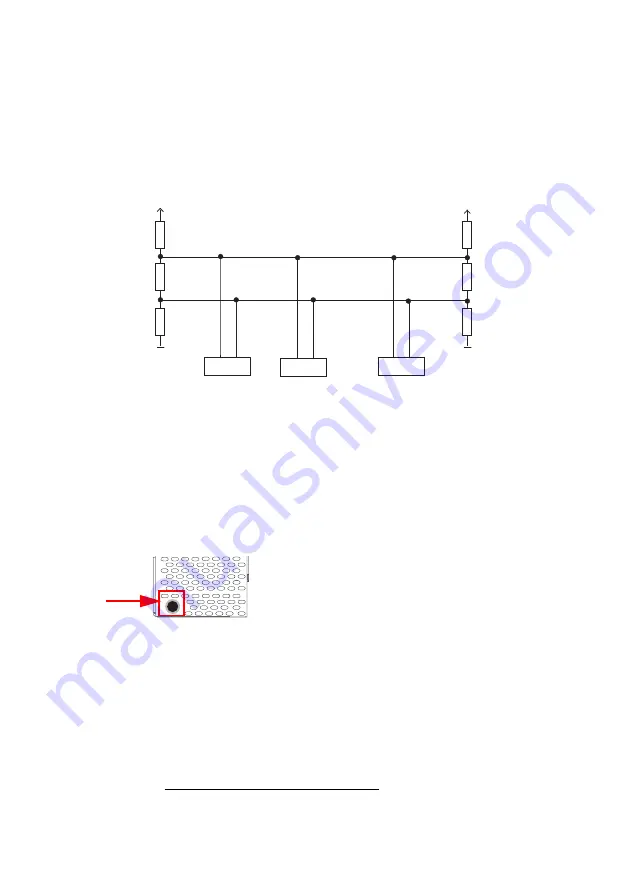
The AS-i/PROFIBUS gateway sends and receives signals on pins 3 and 8 of the
D-SUB connector. The PROFIBUS signal “RxD/TxD-N (data line A)
1
” is located
on pin 8, the signal “RxD/TxD-P (data line B)
1
” is located on pin 3.
Pin 5 (0 V) and pin 6 (5 V) supply 5 V DC for the bus termination resistor.
5.4.1
Terminating resistors on the PROFIBUS network
5.5
Diagnostics interface
The service and diagnostics interface (in conjunction with
AS-i Control Tools
software) is used for communication between the PC and the unit.
5.5.1
Diagnostics port RS 232
The service and diagnostics interface is configured as a mini DIN-6 female and it
is placed at the top of the housing (see section <Overview of terminals, indicators
and operating elements>).
1.
If you measure the DC voltage between RxD/TxD-P (data line B) and RxD/TxD-N (data line A),
RxD/TxD-P (data line B) is the positive pole when the bus is silent.
A
A
A
B
B
B
390
220
390
Host
AS-i Master
AS-i Master
390
220
390
5V
5V
GND
GND
Summary of Contents for CESA-GW-AS-PB
Page 1: ...Description AS i Gateway English Gateway AS i PROFIBUS CESA GW AS PB 749962 1002NH ...
Page 2: ......
Page 4: ......


