background image

CESA-GW-AS-PB  Description

26

6.2

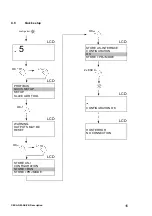
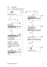
Navigating through the advanced display mode

The device starts up in the classical mode. Pressing the OK button switches to
the advanced mode. To return to the classical mode, the ESC button must be
pressed several times. 
In the advanced mode, the selection menu can be moved up and down by using
the two arrow buttons. Pressing OK switches to the selected function or to the
displayed menu, respectively. Pressing ESC returns to the previous menu. 
To edit a value it must be highlighted  by using the selection bar and then press-
ing OK. The data can be changed by using the arrow-buttons. Changes are con-
firmed with OK. The ESC button cancels the editing process. 
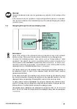
All possible slave addresses are displayed in sequence from 1 A to 31 A and
from 1 B to 31 B. Data for single slaves are displayed along with the addresses
1 A to 31 A.

Warning!

Classical (traditional) mode does not guarantee any protection of the settings of the
device! 
In the classical mode, it is possible to change settings while the device is in operation.
This can lead to failures of the installation/process (for example changing the address
of an AS-i slave).

1.12A

PROFIBUS

AS-I CONTROL

QUICK SETUP

SLAVE ADR.  TOOL

SLAVE TEST TOOL

SETUP

IO + PARAM.TEST

DIAGNOSIS

DISPLAY CONTRAST

ADV. DIAGNOSE

AS-I SAFETY

LANGUAGE

DISPLAY CONTRAST

Information!

Some of the settings in the advanced mode are protected as long as the upstream
fieldbus running. That means that some status information can be displayed only.
To protect the installation/process, many options such as "change address", "write
parameter", "set outputs", etc. cannot  be performed with an active connection to the
control system (active PROFIBUS masters Class 1Bus connection) . In order to  exe-
cute these commands via the display,  the connection  to the control system must be
deactivated first (no  PROFIBUS Master Class 1 connection).

Summary of Contents for CESA-GW-AS-PB

Page 1: ...Description AS i Gateway English Gateway AS i PROFIBUS CESA GW AS PB 749962 1002NH ...

Page 2: ......

Page 3: ...oduction de ce docu ment sous quelque forme que ce soit et toute ex ploitation ou communication de son contenu sont in terdites sauf autorisation écrite expresse Tout manquement à cette règle est illicite et expose son auteur au versement de dommages et intérêts Tous droits réservés pour le cas de la délivrance d un bre vet d un modèle d utilité ou d un modèle de présen tation È vietato consegnare...

Page 4: ......
Page 5: ...1 Dimensions 11 4 2 Connections 11 4 3 Installing in the control cabinet 11 4 4 Removing 12 4 5 Electrical Connection 12 4 6 Startup 13 4 6 1 Switching to advanced display mode 13 4 6 2 Setting the PROFIBUS DP address 14 13 4 7 Connecting AS i Slaves 14 4 8 Error tracing 15 4 8 1 Faulty slaves 15 4 8 2 Error display last error 15 4 9 Quick setup 16 4 10 Addressing 17 4 10 1 Program slave 0 to addr...

Page 6: ... 30 6 4 3 CONTROL FLAGS control program flag memory 30 6 5 QUICK SETUP 31 6 6 SLAVE ADR TOOL 31 6 7 SLAVE TEST TOOL 32 6 8 SETUP configuration of an AS i network 34 6 8 1 AS I SLAVE ADR set change slave address 35 6 8 2 FORCE OFFLINE Switch AS i Master to offline operation 35 6 8 3 OPERATION MODE 36 6 8 4 STORE ACTUAL store currently detected configuration 36 6 8 5 PERMANENT PARA permanent paramet...

Page 7: ... cyclic data 56 7 1 2 1 Options 57 7 1 3 I O Data 59 7 1 3 1 Process data 59 7 1 3 2 EC flags and AS i watchdog 61 7 1 3 3 AS i 16 bit data 61 7 1 3 4 Command interface 62 7 2 DP V1 63 7 3 Restrictions 63 8 Advanced Diagnostics for AS i Masters 64 8 1 List of corrupted AS i Slaves LCS 64 8 2 Protocol analysis Counters for corrupted data telegrams 64 8 3 Offline Phase for Configuration Errors 65 8 ...

Page 8: ...ormity statement according to the EC EMC low voltage and maschinery directive can be sent to by request Additional information can be found in the Festo basic catalogue or in the online catalogue in internet at www festo com Subject to technical modifications ...

Page 9: ... Non compliance may lead to interruptions of the device the connected peripheral systems or plant potentially leading to total mal functioning Warning This symbol warns of an imminent danger Non compliance may lead to personal inju ries that could be fatal or result in material damages and destruction Information Additional information can be found in section Glossary ...

Page 10: ... to monitor the AS i data online via PROFIBUS DP V1 2 2 Technical data The technical data are placed in the data sheet Please view the current version on the web page http www festo com 2 3 AS i specification 3 0 The AS i 3 0 gateways already fulfil the AS i specification 3 0 The previous specifications 2 1 and 2 0 are supported as well Advanced Diagnostics Diagnostics which go far beyond the stan...

Page 11: ...the equipment and conducting any maintenance work under power must exclusively be performed by appropriately qualified personnel In case a failure cannot be eliminated the device must be taken out of operation and inadvertently operation must be prevented Repair work must be performed by the manufacturer only Additions or modifications to the equipment are not permitted and will void the warranty ...

Page 12: ...et The AS i Gateway is installed in the control cabinet on 35mm DIN rails per DIN EN 50 022 55 75 120 7 76 5 6 mm PZ2 0 8 Nm 7 LB IN 2 x 0 5 1 5 mm 2 2 x 0 5 1 5 mm 2 AWG 2 x 24 12 10 10 Information The enclosure of the AS i Gateway is made of stainless steel The unit is also suitable for exposed wall mounting ...

Page 13: ... To remove press the holding clamps 2 down using a screwdriver 1 press the unit firmly against the upper rail guide and lift out 4 5 Electrical Connection 1 2 1 2 3 Information Electrical connections are described in section Electrical connection Information See also section Operation in advanced display mode for further information ...

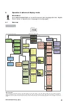
Page 14: ...enu voir page supplémentaire struttura di menu vedi pagina supplementare estructura del menu ver página adicional LCD 12A UNKNOWN SLAVE LCD PROFIBUS QUICK SETUP SETUP SLAVE ADR TOOÖ erweiterter Anzeigemodus advanced display mode mode d affichage étendu modo di visualizzazione avanzata modo de visualisación avanzada LCD PROFIBUS OK QUICK SETUP ASI SAFETY OK LCD PROFIBUS ADDRESS PROFIBUS STATUS LCD ...

Page 15: ...14 2x ESC NEW ADDRESS 000 2x ESC 2x OK OK LCD PROFIBUS ADDRESS OLD ADDRESS 3 NEW ADDRESS 010 4x OK Slave 1 AS i Slave 5 AS i LCD 0 5s Slave 1 AS i Slave 5 AS i AS i prj mode Config error prg enable AS i active U AS i Profibus Power AS i prj mode Config error prg enable AS i active U AS i Profibus Power 5 1 AS i Master LCD 41 SEARCHING SLAVES AS i Master 0 5s 0 5s 24 ...

Page 16: ...ower 24 MISSING SLAVE MISSING SLAVE 2s 2s LCD LCD AS i Master Slave 1 AS Interface Slave 5 AS Interface Slave 24 AS Interface AS Interface 24 LCD set Slave 1 AS Interface Slave 5 AS Interface Slave 24 AS Interface AS Interface prj mode Config error prg enable AS i active U AS i Profibus Power prj mode Config error prg enable AS i active U AS i Profibus Power HOST ERROR NO CONNECTION AS i Master AS...

Page 17: ...CD CONFIGURATION OK LCD PROFIBUS QUICK SETUP SETUP SLAVE ADR TOOL OK LCD WARNING OUTPUTS MAY BE RESET OK OK LCD STORE AS I CONFIGURATION STORE RUN LCD STORE AS INTERFACE CONFIGURATION 2x ESC OK LCD 5 LCD HOST ERROR NO CONNECTION OK STORE PRJ MODE STORE PRJ MODE ...

Page 18: ... SLAVE ADR TOOL CONNECT NEW SLAVE LCD SLAVE ADR TOOL OLD ADDRESS 2 NEW ADDRESS 3 PRG 1x LCD SLAVE ADR TOOL OLD ADDRESS 2 NEW ADDRESS 6 2x ESC LCD 6 UNKNOWN SLAVE LCD SLAVE ADR TOOL OK OLD ADDRESS NEW ADDRESS 3xOK PRG 1x LCD SLAVE ADR TOOL OLD ADDRESS 2 NEW ADDRESS 6 PRG OK Master Slave Modul anschließen Connect module Raccordez le module Collegare il modulo Conecte modulo ...

Page 19: ...elements 5 1 1 CESA GW AS PB Legend 1 RS232 diagnostics port1 2 LEDs 3 D sub connection PROFIBUS interface 4 LC display 5 Push buttons 6 AS i and power supply terminal 1 Only in conjunction with AS i Control Tools 5 2 4 3 5 6 mm PZ2 0 8 Nm 7 LB IN 2 x 0 5 1 5 mm 2 2 x 0 5 1 5 mm 2 AWG 2 x 24 12 10 10 6 1 ...

Page 20: ...be performed only by electrical technicians Information The cable indicated by grey must not have slaves or repeaters connected to it The yellow cable must not have AS i power suppliers or additional masters connected to it Information The function ground can be connected either to the grounding screw or to the terminal The function ground should be made with as short a cable as possible to ensure...

Page 21: ...SI M4 5 mm max Function ground Terminal Signal Description AS i Connection to AS i Circuit ASI PWR Supply voltage for AS i Circuit max 8 A FE Function ground Information For additional information please refer to the section AS i and power supply terminal assignments PIN Designation of the D SUB connector Pin 3 Data line B RxD TxD P Pin 5 DGND 0 V Pin 6 VP 5 V Pin 8 Data line A RxD TxD N 5 4 3 2 1...

Page 22: ... The service and diagnostics interface in conjunction with AS i Control Tools software is used for communication between the PC and the unit 5 5 1 Diagnostics port RS 232 The service and diagnostics interface is configured as a mini DIN 6 female and it is placed at the top of the housing see section Overview of terminals indicators and operating elements 1 If you measure the DC voltage between RxD...

Page 23: ...t match the nominal configuration data or the master is in the startup proc ess This LED flashes if a peripheral fault has been detected for at least one AS i slave on the AS i network If there are configuration errors as well as periphery faults only the configuration error is displayed U AS i The AS i network is sufficiently powered AS i active Normal operation is active prg enable Automatic sin...

Page 24: ... in advanced display mode Mode Switching between configuration mode and protected operating mode and saving the current AS i configuration as the nominal configuration Set Selecting the address of and assigning an address to a slave OK Changing to the advanced display mode ESC This button is used to leave the advanced display mode ...

Page 25: ... TOOL SETUP LANGUAGE SLAVE ADR TOOL CONNECT OLD ADDRESS 21A NEW ADDRESS 03B PRG 30A 8 31A 9 1B 0 2B E 3B 0 WARNING OUTPUTS MAY BE LOOSE CONTROL SLAVE ADR 21A OK BINARY INPUTS 1 BINARY OUTPUTS ANALOG INPUTS ANALOG OUTPUTS 0 1 1 2 F F 0A72 0000 1 32767 OVERFL 1 PARAM PERM PARAM PERM CONF SET AND HOST MAY SLAVE TEST TOOL SLAVE ADR 21A TEST 4B E 5B 0 30B 8 31B 9 AS I SLAVE ADDR OLD ADDRESS NEW ADDRESS...

Page 26: ...0A 1A 7A28 C TYPE CONFLICT LCS LIST OF CORRUPTED SLAVES RESET ERROR COUNTERS RESET 1A 0 31A 65535 1B 34 30B 0 ERROR COUNTERS LCS FAULT DETECTOR 1A X 2A 3A 4A X 5A X 30A X 31A 1B X 2B X 3B X 4B X 5B X 30B X 31B X SAFETY ORIENTED SLAVES 1 2 XX 3 RR 30 RX 31 XR HELP X O K R CH RELEASED SAFETY SLAVES SAFETY MONITOR SAFE SUBST VAL FLAGS 0131 05 0000 0001 0011 0001 0000 0101 1 PERIPHERY_OK 0 OFFLINE_REA...

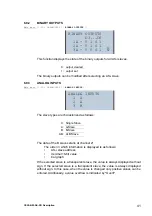
Page 27: ...the addresses 1 A to 31 A Warning Classical traditional mode does not guarantee any protection of the settings of the device In the classical mode it is possible to change settings while the device is in operation This can lead to failures of the installation process for example changing the address of an AS i slave 1 12A PROFIBUS AS I CONTROL QUICK SETUP SLAVE ADR TOOL SLAVE TEST TOOL SETUP IO PA...

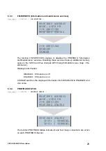
Page 28: ... ADR OVER PB Set address via PROFIBUS Main menu PROFIBUS ADR OVER PB By using this function the option of changing the address via PROFIBUS can be switched on and off CHANGE the display switches between ENABLED and DISABLED PROFIBUS ADDRESS ADDR OVER PB I M SERVICES PROFIBUS STATUS PROFIBUS ADDRESS OLD ADDRESS 099 NEU ADRESS 003 PROFIBUS ADDRESS ADDR OVER PB I M SERVICES PROFIBUS STATUS ADDR OVER ...

Page 29: ... chap Re strictions Displayed information CHANGE switches the displayed information from DISABLED to ENABLED and vice versa 6 3 4 PROFIBUS STATUS Main menu PROFIBUS PROFIBUS STATUS The function PROFIBUS Status indicates if and how many connections are active on each PROFIBUS channel PROFIBUS ADDRESS ADDR OVER PB I M SERVICES PROFIBUS STATUS I M SERVICES ENABLED CHANGE DISABLED I M service is off E...

Page 30: ...c channel 0 not active 1 active DP V1 acyclic channel 0 not active 0 number of connections CONTROL INFO CONTROL RUN CONTROL FLAGS CONTROL INFO status of the control programm CONTROL RUN start stop the control programm CONTROL FLAGS read change the control programm CONTROL INFO START BIT SET RUNNING CYCLE TIME ACT 2MS MAX 5MS START BIT SET the control program has been started START BIT RESET the co...

Page 31: ... displays the selected row After pressing OK the display mode changes and it is now possible to select indi vidual flags using the soft keys The selected flag is then displayed in binary for mat at the top row Pressing OK again enables editing the selected binary value CONTROL RUN RUN CHANGE RUN The control program has been started The control program can be stopped even if the start bit is set fo...

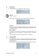
Page 32: ...ion and the detected slaves on the AS i network as the active configuration The gateway remains in configuration mode Pressing ESC leaves this menu and switches back to the main menu 6 6 SLAVE ADR TOOL Main menu SLAVE ADR TOOL This function enables setting and changing the addresses of both new and al ready configured AS i slaves This function replaces the handheld AS i address programming device ...

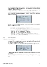
Page 33: ...is displayed pointing out that it is possible during this test that outputs are set and that the host may loose control over the network Pressing the OK button continues with the actual test ESC cancels the process In the proceeding menu the slave to be tested has to be selected by entering the slave address Afterwards testing the selected slave is started by confirming the menu entry Test SLAVE A...

Page 34: ...the tested slave The following information is displayed Address of the tested slave Display of a configuration error if present Binary inputs digital inputs Binary outputs digital outputs Analog inputs Analog outputs Param actual parameters Perm Param permanent parameters Config actual configuration Perm Conf permanent configuration SLAVE TEST TOOL SLAVE ADR 21A TEST ...

Page 35: ... available SLAVE ADR 21A OK BINARY INPUTS 1 BINARY OUTPUTS 1 ANALOG INPUTS 0000 1 32767 OVERFL ANALOG OUTPUTS 0 32767 OVERFL ANALOG OUTPUTS 0 1 1 2 PARAM F PERM PARAM F CONFIG 0A72 PERM CONF 0A72 AS I SLAVE ADDR FORCE OFFLINE OPERATION MODE STORE ACT CFG PERMANENT PARAM PERMANENT CFG ADDR ASSISTANT LOS AUTO ADDR ENABLE FACTORY RESET ...

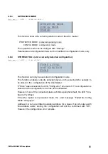
Page 36: ...slave With Change this status can be changed Switching the AS i master to offline operation puts the AS i network into the safe state The AS i master must be offline if an AS i slave needs to be readdressed via the IR interface AS I SLAVE ADDR set edit AS i slave address FORCE OFFLINE switch AS i master to offline operation OPERATION MODE operation mode STORE ACT CFG store current configuration PE...

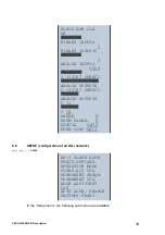
Page 37: ... in the configuration of the AS i Master If Store was successful the LED Config error is turned off The configuration is stored and the configuration error has been eliminated However if one of the connected slaves exhibits a peripheral fault the LED Con fig error will flash If the AS i master is in protected mode the error message Failed No Config Mode will appear Address 0 is not a permitted ope...

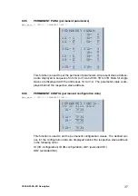
Page 38: ...yed behind the respective slave address 6 8 6 PERMANENT CONFIG permanent configuration data Main menu SETUP PERMANENT CONFIG This function is used to set the permanent configuration values The defined val ues for the configuration data are displayed behind the respective slave address in the following order IO I O configuration ID ID configuration xID1 extended ID1 xID2 extended ID2 PERMANENT PARA...

Page 39: ...ration for the AS i Master or directly in the advanced display mode 2 All AS i slaves have to be addressed to 0 or to the desired address The slaves must be disconnected from the AS i network 3 Start the AS i address assistant 4 Now the AS i slaves are connected to the AS i network one at the time in the order specified by the AS i address assistant The last line displayed for the AS i address ass...

Page 40: ... the master to the factory default settings The Reset is done by selecting menu point DO RESET 6 9 IO PARAM TEST Main menu IO PARAM TEST The following warning message will be displayed before entering this menu Empty field LOS bit deleted X LOS bit set AUTO ADDRESS ENABLE CHANGE Enable automatic address assignment is released Disable automatic address assignment is locked FACTORY RESET DO RESET Wa...

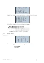
Page 41: ...y inputs for all AS i slaves WARNING OUTPUTS MAY BE SET AND HOST MAY LOSE CONTROL OVER THE AS I MASTER BINARY INPUTS BINARY OUTPUTS ANALOG INPUTS ANALOG OUTPUTS PARAMETER BINARY INPUTS State of the binary inputs BINARY OUTPUTS State of the binary outputs ANALOG INPUTS State of the analog inputs ANALOG OUTPUTS State of the analog outputs PARAMETERS Value of the current AS i parameter BINARY INPUTS ...

Page 42: ...el 2 The order in which information is displayed is as follows AS i slave address decimal 16 bit value bar graph If the selected slave is a transparent slave the value is always displayed without sign If the selected slave is a transparent slave the value is always displayed without sign In this case when the value is changed only positive values can be entered Additionally a value overflow is ind...

Page 43: ...ected slave is a transparent slave the value is always displayed without sign If the selected slave is a transparent slave the value is always displayed without sign In this case when the value is changed only positive values can be entered Additionally a value overflow is indicated by Overfl The analog outputs can be changed after selecting an AS i slave ANALOG IN 1 0 2500 1 17898 2 32767 OVERFL ...

Page 44: ...rameters can be changed after selecting a slave address 6 10 DIAGNOSIS Main menu DIAGNOSIS For additional information refer to chap Advanced Diagnostics for AS i Mas ters PARAMETER 1A 0 2A 2 3A F 4A E 5A 3 FLAGS ACTUAL CONFIG LPF AS I MASTER FLAGS Display of the EC Flags ACTUAL CONFIG Display of the current configuration LPF List of Peripheral Faults AS I MASTER Display of the software states ...

Page 45: ...L 0 AUTO_ADDR_ASN 0 LDS O 1 CONFIG_OK 1 AUTO_ADDR_ENA 0 OFFLINE 1 DATA_EXCH_ACT Byte Byte value 27 26 25 24 23 22 21 20 Bit 7 6 5 4 3 2 1 0 Byte 1 Bit 0 Periphery_OK This flag is set if none of the AS i slave signals a peripheral fault Byte 2 Bit 7 Offline_Ready The flag is set if the AS i master is offline Bit 6 AS i Pwr Fail The flag is set if the AS i circuit is not sufficiently powered Bit 5 N...

Page 46: ... 3 Bit 0 Data_Exch_Act If the flag Data Exchange Active is set the data exchange with AS i slaves is possible during the data exchange phase If the bit is not set the data exchange with AS i slaves is inhibited Instead of data telegrams READ_ID telegrams will be sent The bit is set by the AS i master at the beginning of the offline phase Bit 1 Offline This bit is set if the operating mode is suppo...

Page 47: ...6 10 3 LPF List of Peripheral Faults Main menu DIAGNOSIS LPF LIST OF PERIPH FAULTS This list shows the list of slaves which have triggered peripheral faults LPF X O K The configuration data for the detected AS i slave agree with the designed in configuration data D Detected Only An AS i slave is detected at this address but it was not designed in P Projected Only An AS i slave was designed in at t...

Page 48: ...ation refer to section Advanced Diagnostics for AS i Mas ters 6 11 1 ERROR COUNTERS Main Menu ADV DIAGNOSIS ERROR COUNTERS Empty field Peripheral O K X Peripheral fault VERSION 20000919 FEATURE STRING ZEFOD1 AS ER VERSION date of the firmware FEATURE STRING feature string of the AS i masters ERROR COUNTER LCS FAULT DETECTOR ERROR COUNTER error counter LCS list of slaves that caused a configuration...

Page 49: ...of the slaves which have triggered a configuration error Main menu ADV DIAGNOSIS LCS This list contains entries for all AS i slaves that were responsible for at least one intermittent configuration error since the list was last read or since the AS i mas ter was turned on LCS LIST OF CORRUPTED SLAVES RESET 1A X 2A 3A 4A X 5A X 30A X 31A 1B X 2B X 3B X 4B X 5B X 30B X 31B X empty field no error X A...

Page 50: ... the AS i fault detec tor since the last Reset The section Actual lists the currently present error messages of the AS i fault detector The following error messages are displayed Duplicate address displaying of 2 lowest slave addresses with duplicate addresses Earth faults Noise Over voltage Optionally the absence of the redundant 24V for some single masters may be displayed 6 12 AS I SAFETY Main ...

Page 51: ...can not be evaluated individually if the substitution of safety slaves input data was disabled in menu command interface function profile or slave value substitute SAFETY SUBST VALUE In this case both channels must have the same state otherwise the indication will not be proper 6 12 2 SAFETY MONITOR Main menu AS I SAFETY SAFETY MONITOR SAFETY SLAVES safety oriented slaves SAFETY MONITOR safety mon...

Page 52: ...in menu AS I SAFETY SAFETY SUBST VAL This function enables activation deactivation of the code substitute function for safe slaves SUBSTITUTE values The safety code sequences are replaced by the following values NO SUBSTITUTE The safety code sequences are transmitted via the input data SAFETY MONITOR DIAGNOSIS ADDR 17 MODE SORT V1 STATUS OK CHANNEL 1 OFF CHANNEL 2 OFF 1 32 GREEN SAFE SUBST VAL SUB...

Page 53: ... to select the line with the bar Confirm your selection with OK bar flashes Use the arrow keys to set the display contrast Use OK to apply the setting The factory settings are invoked from the DEFAULT field If the contrast is set so that the display can no longer be read it can be reset to the factory default setting as follows Shut the unit off Press the MODE and SET keys and hold them down Shut ...

Page 54: ...rt these functions DP diagnostics single master PDU byte user byte DP DP V1 user 1 station_status 1 4 2 station_status 2 4 3 station_status 3 4 4 master address 4 5 ident high 4 6 ident low 4 7 1 header 4 4 8 2 type 4 9 3 slot 4 10 4 spec 4 11 5 ec flags high 4 12 6 ec flags low 4 13 7 delta 0 7 4 14 8 delta 8 15 4 20 14 delta 56 63 4 21 15 LPF 0 7 4 28 22 LPF 56 63 4 Tab 7 2 ec flags high bit 0 p...

Page 55: ...s when to set the ExtDiag bit can be chosen using the user parame ters or the commands of the command interface The GSD file includes the following presettings The diagnosis transmitts ec flags delta list and LPF ExtDiag will be set if ConfigError 1 and APF 1 ExtDiag will not be set if there is a periphery fault bit 6 noise bit 7 duplicate address ec flags low bit 0 configuration error bit 1 slave...

Page 56: ...ve the following meanings DP parameters single master PDU byte user byte DP DP V1 user default 1 Station_Status 4 2 WD_Fact_1 4 3 WD_Fact_2 4 4 min Tsdr 4 5 Ident High 4 6 Ident Low 4 7 Group_Ident 4 8 1 DPV Status 1 4 8016 9 2 DPV Status 2 4 0016 10 3 DPV Status 3 4 0016 11 4 User Byte 1 4 0B16 12 5 User Byte 2 4 0616 13 6 User Byte 3 4 0016 Tab 7 3 user byte 1 27 26 25 24 23 22 21 20 LPF D F def...

Page 57: ...ostics 0 Delta list will not be transmitted F 1 EC flags will be transmitted in the diagnostics 0 EC flags will not be transmitted FD If this bit is set the PROFIBUS diagnostics is refreshed only if the PROFIBUS norm dictates this freeze diagnostics In doubt the data of the PROFIBUS masters diagnostics are not up to date CS 1 ExtDiag will be set if the LCS is not empty 0 ExtDiag will not be set if...

Page 58: ...he process data channel and do not have to be requested by the slower DP V1 commands Maximally 8 modules can be configurated The detailed possibilities Length description 4 bytes digital input slaves 0 7 8 bytes digital input slaves 0 15 12 bytes digital input slaves 0 23 16 bytes digital input slaves 0 31 20 bytes digital input slaves 0 7B 24 bytes digital input slaves 0 15B 28 bytes digital inpu...

Page 59: ...interface 34 bytes management command interface 36 bytes management command interface Tab 7 10 Length description 24 bytes analog input slaves 29 31 56 bytes analog input slaves 25 31 88 bytes analog input slaves 21 31 120 bytes analog input slaves 17 31 128 bytes analog input slaves 16 31 16 bytes analog input slaves 14 15 Tab 7 11 Length description 24 bytes analog output slaves 29 31 56 bytes a...

Page 60: ...og output data circuit 1 dynamic1 2 bytes 128 bytes analog input data circuit 2 dynamic1 2 bytes 128 bytes analog output data circuit 2 dynamic1 Tab 7 13 Length description 2 bytes flags and detector circuit 1 2 bytes flags and detector circuit 2 Tab 7 14 byte 27 26 25 24 23 22 21 20 0 flags slave 1 1A F3 F2 F1 F0 D3 D2 D1 D0 1 slave 2 2A slave 3 3A 2 slave 4 4A slave 5 5A 3 slave 6 6A slave 7 7A ...

Page 61: ... 20B slave 21B 27 slave 22B slave 23B 28 slave 24B slave 25B 29 slave 26B slave 27B 30 slave 28B slave 29B 31 slave 30B slave 31B Flags input data output data F0 ConfigError Offline F1 APF LOS master bit F2 PeripheryFault ConfigurationMode F3 ConfigurationActive ProtectedMode Tab 7 16 ConfigError 0 config ok 1 config error APF 0 AS i power ok 1 AS i power fail PeripheryFault 0 periphery ok 1 perip...

Page 62: ...ar slave are being transmitted both cyclically and acyclically with the command interface or via DP V1 connections the acyclically transmitted values will be overwritten by the cyclically transmitted values AS i 16 bit data can be transmitted in a reserved data area Therefore accessing analog data is as easy as accessing digital data Offline 0 online 1 offline LOS Master Bit 0 offline by configerr...

Page 63: ... slave 31 n 8 channel 1 low byte 3 slave 31 n 8 channel 2 high byte 4 slave 31 n 8 channel 2 low byte n 3 slave 31 channel 3 slave 31B channel 1 high byte n 2 slave 31 channel 3 slave 31B channel 1 low byte n 1 slave 31 channel 4 slave 31B channel 2 high byte n slave 31 channel 4 slave 31B channel 2 low byte Tab 7 17 Request byte 27 26 25 24 23 22 21 20 1 command 2 T circuit 3 request parameter by...

Page 64: ...umbers of DP V1 connections to class 2 masters have to be re stricted Information I M service contains data for identification and maintenance This service is on by default Switching the services off provides additional memory into SPC3 This changes the DP VD length limit Restrictions due to the SPC3 MSC1 inputs data outputs data single master 288 bytes1 diagnosis 62 bytes parameter single master ...

Page 65: ...sted in the LCS at the position of AS i slave with address 0 8 2 Protocol analysis Counters for corrupted data telegrams The AS i master with advanced diagnostics provides a counter for telegram repe titions for each AS i slave The counter counts up every time a corrupted data tel egram has been found making it possible to determine the quality of the trans mission if only a few telegrams are corr...

Page 66: ... critical slaves only the error message is sent to the host but AS i is still running Like the advanced diagnostics the parameterization offline phase on configura tion error is also supported by AS i Control Tools Command Characteristics Offline because of configuration error There are two options to reset the error message OFFLINE BY LOS 1 Deleting the complete LOS list on the affected AS i netw...

Page 67: ...use are insufficiently shielded frequency inverters or improperly routed cables Noises is indicated on the master s display as well as in AS i Control Tools 8 4 4 Over voltage Detector Over voltages are present if the conductors of an AS i network that normally are routed electrically symmetrical with respect to machine ground are strongly elec trically raised A cause can for example be startup pr...

Page 68: ...rol Tools This way the device driver is copied into the previous designed folder in AS i Control Tools and should be recognized automatically The Windows software AS i Control Tools enables the user to easily configure the AS i network 1 Plug the PROFIBUS Master Simulator or a serial PROFIBUS Master respectively into the D SUB connector of the AS i PROFIBUS Gateway and connect the device to the PC...

Page 69: ...ion 68 6 5 Select Master AS i configuration The AS i configuration editor will be started All detected and configured AS i slaves are displayed in this win dow 7 Click on a slave to open the dialog window slave configuration ...

Page 70: ...bles the user to edit a slave address and to set AS i parameters or AS i configuration data Additionally inputs and outputs can be tested 8 Click the second button on the right side of the tool bar to get a graphical display of AS i Control Tools ...

Page 71: ...ta Furthermore an AS i Address Assistant is available allowing to perform an ad dress change of a new AS i slave to the desired address as soon as it is con nected to the AS i network The desired AS i configuration can be created offline ahead of time and can be stored to a file When setting up the system the AS i slaves are then simply connected one at a time to the AS i network Further de script...

Page 72: ...ivation phase 43 The AS i master starts the normal operating mode 70 Hardware error The AS i master s EEPROM cannot be written 71 Wrong PIC type 72 Hardware error wrong PIC processor 73 Hardware error wrong PIC processor 74 Checksum error in the EEPROM 75 Error in the internal RAM 76 Error in the external RAM 77 AS i control software error Stack overflow AS i control II 78 AS i control software er...

Page 73: ... address is occupied by this superfluous slave In the protected mode the slave addresses which caused any configuration error can be displayed by pressing the SET button AS i master without graph ical display are not able to differentiate between a missing slave an incorrect slave or a redundant slave All incorrect addresses are displayed By pressing the SET button 5 sec the displayed address star...

Page 74: ...of the slave De pending on the mode protected mode or configuration mode and on the current configuration the detected slave will be activated After each data exchange with all AS i slaves exactly one inquiring call is sent to one slave address Hence the AS i cycle always includes one more telegram than the number of activated slaves LAS Autoprog flags Auto Address Enable flag from the operating s...

Page 75: ...o see configuration mode This mode is intended for normal operation since all AS i protective measures are activated ID code The ID code is set by the slave manufacturer and cannot be changed The AS i Association determines the ID codes which are assigned for a particular class of slaves For example all A B slaves have ID code A ID1 Code extended ID1 code The ID1 code is set by the slave manufactu...

Page 76: ...laves do not match A configuration error could be due to the fol lowing Missing slave A slave entered in the LPS is not available Wrong type of slave The slave profile of the connected slave does not comply with the configuration Unknown slave A connected slave is not entered in the LPS LAS List of Activated Slaves The master exchanges I O data with the slaves entered in the LAS In protected mode ...

Page 77: ...guration a configuration error exists Permanent parameter The parameters saved in the master and sent to the slave after startup of the master during the activation phase Configuration mode During the configuration mode the master exchanges data with all connected slaves no matter which of the slaves were configured Thus in this mode it is possible to operate a system without the necessity to conf...

Page 78: ...CESA GW AS PB Description 77 AS i 2 0 slaves do not have extended ID1 and ID2 codes A 2 1 or 3 0 AS inter face master enters in this case an F for each of the extended ID1 and ID2 codes ...

Reviews: