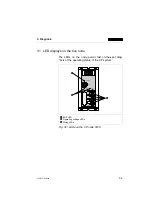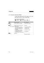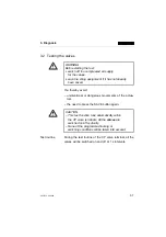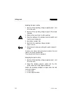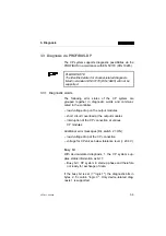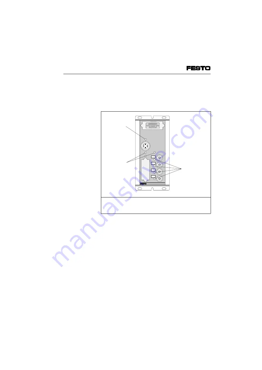
3.1 LED displays on the bus node
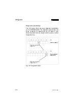
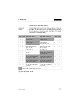
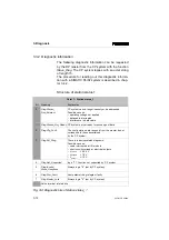
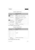
The LEDs on the node permit fast on-the-spot diag-
nosis of the operating status of the CP system.
1
2
3
BUS LED
Operating voltage LEDs
String LEDs
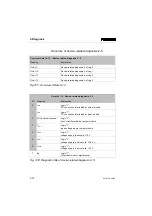
Fig. 3/1: LEDs on the CP node FB13
0
1
3
2
SAVE
POWER
24 VDC
POWER V
ERROR
PROFIBUS-DP
BUS ERROR
3
2
1
3. Diagnosis
CP FB13-E 9904b
3-3
Summary of Contents for Compact Performance CP-FB9-E
Page 12: ...Chapter 1 Installation 1 Installation CP FB13 E 9904b 1 1 ...
Page 30: ...Chapter 2 Commissioning 2 Commissioning CP FB13 E 9904b 2 1 ...
Page 70: ...Chapter 3 Diagnosis 3 Diagnosis CP FB13 E 9904b 3 1 ...
Page 95: ...3 Diagnosis 3 26 CP FB13 E 9904b ...
Page 96: ...Appendix A Technical specifications A Technical specifications and index CP FB13 E 9904b A 1 ...

