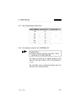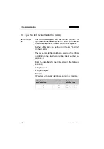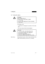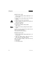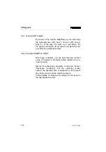
Starting the test routine
1. Switch off the operating voltage supplies (pins 1 and
2) at the node.
2. Switch off the operating voltage supply at the output
modules.
3. Remove the cover from the DIL switches.
4. Note the settings of the address selector switch and
the DIL switch elements.
5. Set station number 199.
6. Switch on the operating voltage supplies
(pins 1 and 2).
7. Start the test routine by setting DIL switch element 1
to OFF.
If errors occur when the test routine is started, the red
LED on the node will flash fast.
The process must then be repeated.
Stopping the test routine
1. Switch off the operating voltage supplies (pins 1 and
2) at the node.
2. Reset the address selector switch and the DIL
switch elements to their original positions.
Switch the operating voltages on again when the test
routine is finished:
•
on the node
•
on the output modules
3. Diagnosis
3-8
CP FB13-E 9904b
Summary of Contents for Compact Performance CP-FB9-E
Page 12: ...Chapter 1 Installation 1 Installation CP FB13 E 9904b 1 1 ...
Page 30: ...Chapter 2 Commissioning 2 Commissioning CP FB13 E 9904b 2 1 ...
Page 70: ...Chapter 3 Diagnosis 3 Diagnosis CP FB13 E 9904b 3 1 ...
Page 95: ...3 Diagnosis 3 26 CP FB13 E 9904b ...
Page 96: ...Appendix A Technical specifications A Technical specifications and index CP FB13 E 9904b A 1 ...

