

DDPC
Festo – DDPC –
201905b
English
9
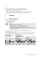
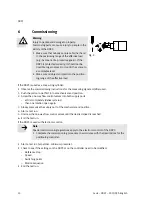
5.3
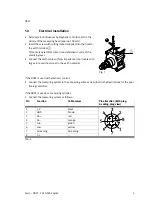
Electrical installation
Avoid external influences by magnetic or ferritic parts in the
vicinity of the measuring head (approx. 100 mm).
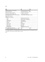
Insert the screw with cutting thread supplied into the hole for
the earth terminal
7
.
This ensures electrical contact is established in spite of the
anodising layer.
Connect the earth cable with low impedance (short cable with
large cross-sectional area) to the earth potential.
Fig. 7
7
If the DDPC is used with electronic control:
Connect the measuring system to the connecting cable as described in the descriptions for the posi
tioning controller.
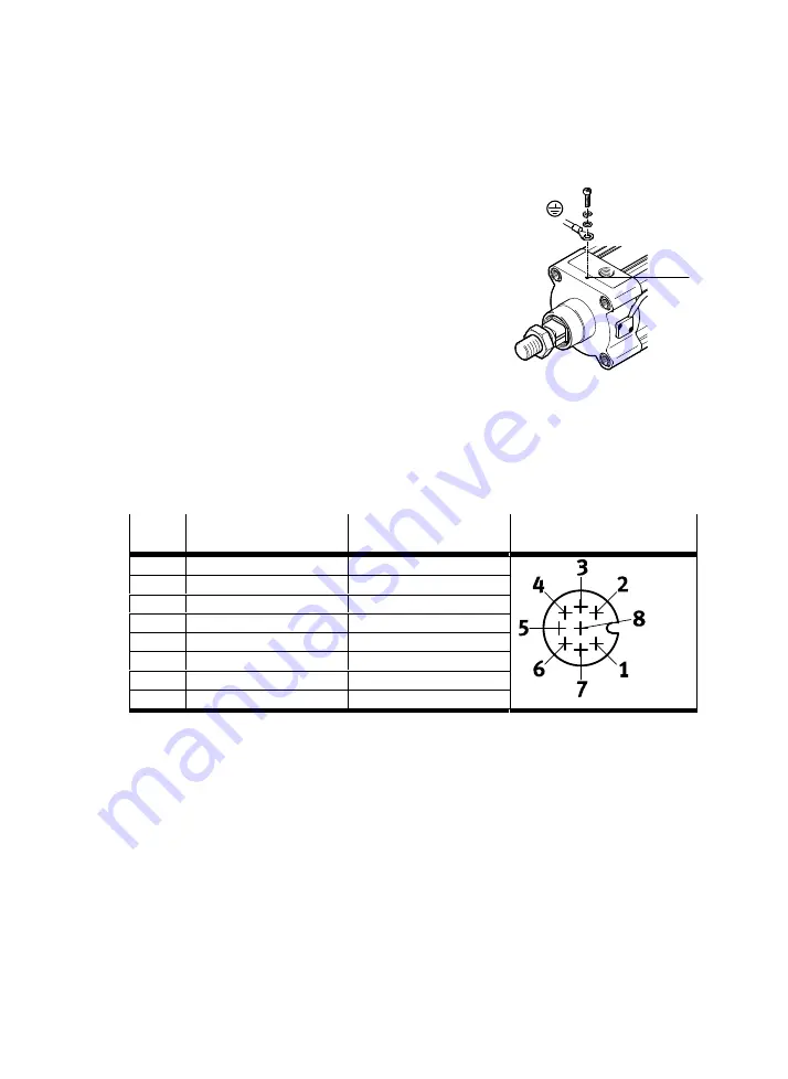
If the DDPC is used as a measuring cylinder:
Connect the measuring system as follows:
Pin
Function
Cable colour
Pin allocation (M12-plug,
A-coding, plug view)
1
5 V
black
2
GND
brown
3
sin+
red
4
sin–
orange
5
cos–
green
6
cos+
yellow
7
Screening
Screening
8
n. c.
–
Tab. 4


