14 / 48
Festo 7DGE_25-63_ZR_KFb_en
4
Repair steps
This chapter describes how to dismantle, repair and assemble the toothed belt axis DGE-…-ZR. This is done by first dis-
mantling the device into individual modules (subsequent sections deal with the repair of these modules). Depending on
the cause of the defect to be eliminated it may be necessary to exchange several components. The cause of a defect must
therefore always be determined before starting a repair.
Note
The repair should preferably be carried out on a stable and flat work surface with storage for small parts. It is also pos-
sible to repair the toothed belt axis in installed condition, if required.
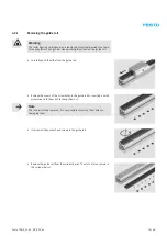
4.1
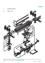
Dismantling the toothed belt axis
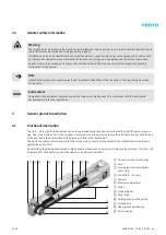
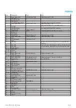
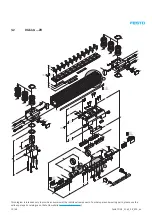
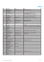
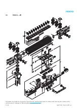
The toothed belt axis DGE-…-ZR comprises the following modules:
• Cylinder barrel
• Drive cover with toothed belt pulley and drive as well as clamp for the cover strip
• Piston with adapter and cover strip guide
• Slide with recirculating ball bearings (only with version DGE-…-KF) on guide rail, driven via moment compensator on
the piston.
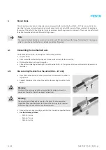
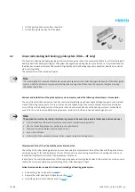
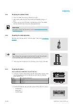
4.1.1
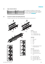
Disconnecting the slide from the piston (DGE-…-KF only)
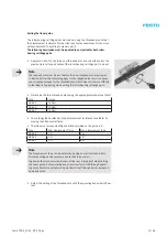
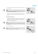
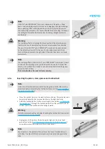
• Place the toothed belt axis on the work surface as shown with the slide fac-
ing upwards.
• Support the piston to the side of the hole for the securing pin with a sturdy
object.
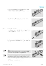
Warning
Driving out the securing pin without supporting the piston can result in
damage to the piston (risk of breakage/deformation).
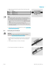
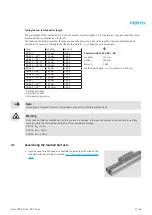
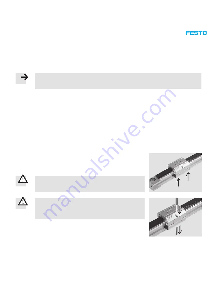
Warning
The securing pin is flattened on one side. Therefore do not use punches
larger than those specified below to drive out the securing pin as the seat
of the securing pin does not have a uniform diameter.
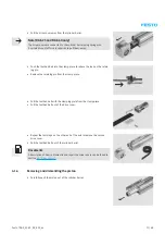
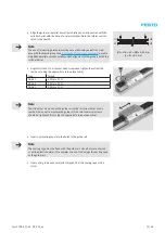
• Drive out the securing pin using a punch with a diameter as specified below.
• Use the following punches:
– DGE-25: 5 mm ø
– DGE-40: 7 mm ø
– DGE-63: 9 mm ø
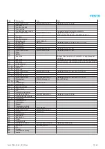
Summary of Contents for DGE-25 ZR RF Series
Page 47: ......
Page 48: ......
Page 49: ...Operating instructions en Toothed belt pretension test equipment 7Tension01_TBb_en...


