22 / 48
Festo 7DGE_25-63_ZR_KFb_en
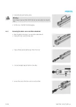
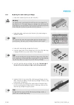
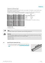
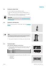
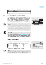
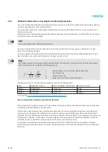
• Tighten the screws of the roller bearing cartridges using the appropriate
torque (see table).
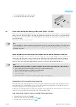
Type
Torque
DGE-25
1.2 Nm ± 10 %
DGE-40
2.9 Nm ± 10 %
DGE-63
9.9 Nm ± 10 %
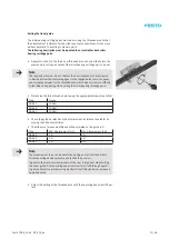
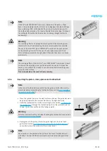
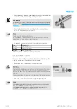
Note
Check the guide backlash, operating behaviour and displacement force
across the full length of the guide rail once more after tightening the screws.
Proceed as follows in the event of deviations from the stipulations:
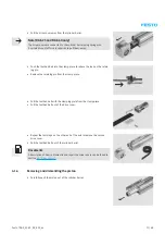
• Loosen the screws of the roller bearing cartridges
opposite the stop side
only
.
• Loosen the threaded pins and repeat the setting procedure.
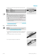
• Then tighten the screws of the roller bearing cartridges using the appro-
priate torque (see table).
• Fill the guide system with the specified grease (see section
the recirculating ball bearing guide”
4.2.3
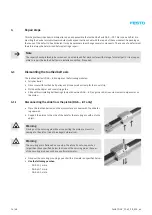
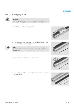
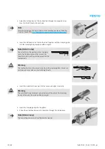
Installing the guide rail with slide
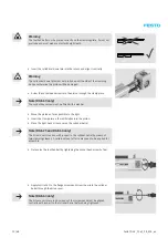
Warning
The play of the roller bearing cartridges must be set before installation
(see section
4.2.2 “Replacing the roller bearing cartridges”
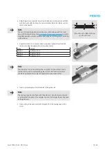
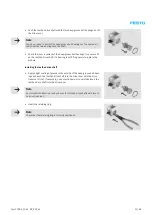
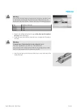
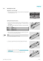
• Carefully push the slide onto the guide rail if you have not already done so.
Make sure that none of the bearings come out of the roller bearing car-
tridges.
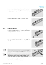
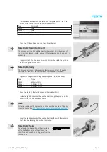
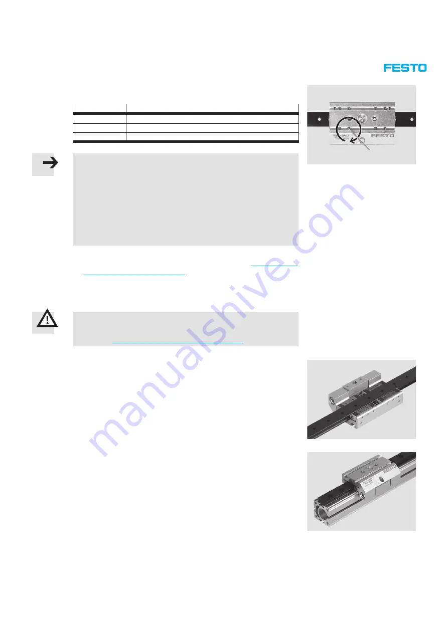
• If necessary, insert the slot nuts into the cylinder barrel.
• Place the guide rail with slide on the cylinder barrel.
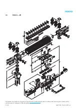
Summary of Contents for DGE-25 ZR RF Series
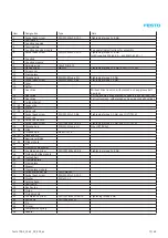
Page 47: ......
Page 48: ......
Page 49: ...Operating instructions en Toothed belt pretension test equipment 7Tension01_TBb_en...


