DNCKE−...−S / KEC−...−S
Festo DNCKE−...−S / KEC−...−S 1002a English
36
S
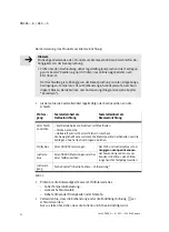
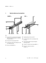
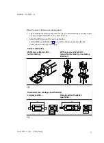
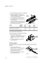
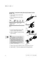
Place the clamping unit in the intended position.
S
Turn the mounting screws until they are equally tight.
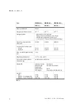
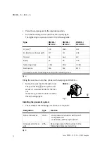
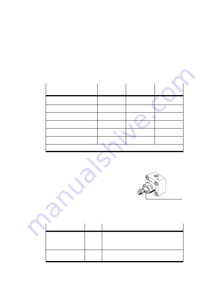
The tightening torques are listed in the following table:
Type
DNCKE−/
KEC−40−...
DNCKE−/
KEC−63−...
DNCKE−/
KEC−100−...
L1 [mm]
*)
178
208.5
287
ZJ+ [mm] (plus stroke length)
277
315
408
TG [mm]
38
56.5
89
E [mm]
54
80
126
Tightening torque
5 Nm
8 Nm
10 Nm
Nominal size
M6
M8
M10
*) Dimension varies depending on setting of the adjusting screw
Fig.6
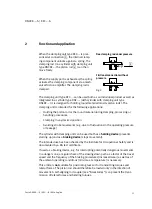
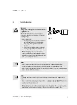
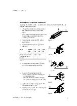
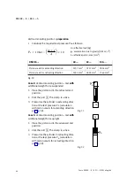
Fitting the work load onto the cylinder with clamping unit DNCKE−...:
S
Fasten the work load to the piston rod.
The spanner flat
aJ
on the piston rod
serves as a counter holder for the lock
nut.
If necessary, secure the lock nut with a
thread locking agent.
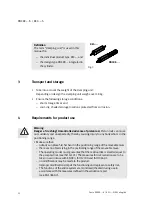
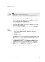
Installing the pneumatic system
S
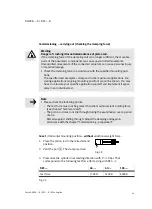
Check whether the following accessories are required:
Designation
Type
Function
Non−return valves
HGL−...
− slow pressure reduction with loss of
−
compressed air
− redundancy with stop function"
Compensation reser
voir
VZS−...
Reducing pressure fluctuations in the
following compressed air string
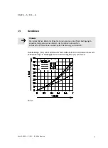
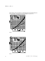
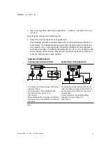
Fig.8
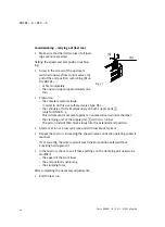
Fig.7
DNCKE−...
aJ

