8.2
Performing commissioning
Running noises during operation
Identical axes can generate different running noises depending on the paramet
erisation, mode of operation, type of mounting, installation environment and com
ponents.
Requirement
–
Mounting of the drive system checked.
–
No foreign objects in the movement space of the propulsion system.
–
No mechanical overload of the axis and dynamic setpoint deviation not
exceeded (e.g. overrunning the end position) due to force and torque peaks.
•
Commissioning of the drive system (e.g. control and homing)
è
Instruction
manual for drive axis, www.festo.com/sp.
9
Operation
WARNING!
Risk of injury due to unexpected movement of components.
•
Protect the positioning range from unwanted intervention.
•
Keep foreign objects out of the positioning range.
•
Perform commissioning with low dynamic response.
10
Maintenance
10.1
Safety
WARNING!
Unexpected movement of components
Injury due to impact or crushing.
•
Before working on the product: secure the slide to prevent unintentional
movement.
CAUTION!
For vertical or slanted mounting position: when power is off, moving parts can
travel or fall uncontrolled into the lower end position.
Injury due to impacts or crushing.
•
Bring moving parts of the product into a safe end position or secure them
against falling.
10.2
Cleaning
1. Clean the product with a soft cloth. Do not use aggressive cleaning agents.
2. If necessary, clean the guide rail with a soft lintfree cloth without detergent.
Then apply a thin layer of lubricant to the guide rail.
10.3
Lubrication
Lubrication interval and accessories
NOTICE!
The lubrication interval S
int
is dependent on the load acting on the product.
Load factors include e. g.:
•
Dusty and dirty environment
•
Nominal stroke
>
2000 mm or
<
300 mm
•
Speed
>
2 m/s
•
Ambient temperature
>
+40 °C
•
Service age of product
>
3 years
•
Travel profile matches triangular operation (frequent acceleration and brak
ing)
If one of these factors applies:
•
Halve lubrication interval S
int
.
If several factors apply at the same time:
•
Divide service interval S
int
by four.
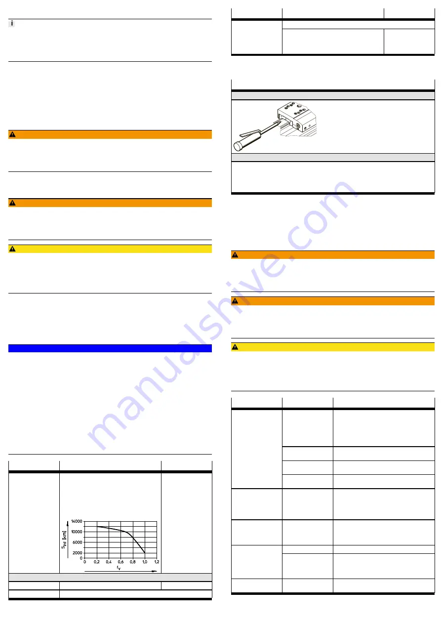
Lubrication
Recirculating ball bearing guide
Guide rail
Lubrication interval
–
Calculate the comparative loading factor f
v
using the formula for combined loads
è
–
Lubrication intervals S
int
as a function of the
load comparison factor f
v
can be taken from
the diagram.
If required, e.g. if the
grease layer is insuffi
cient.
Accessories
è
Lubrication point
Lubrication hole
Surface
Lubricant
Roller bearing grease LUBKC1
Lubrication
Recirculating ball bearing guide
Guide rail
Pressure grease gun with pinpoint nozzle LUB1, 647958
Grease gun
–
Lubrication adapter, axial output,
LUB1TRI, 647959
–
Lubrication adapter, radial output,
LUB1TRL, 647960
–
Tab. 7 Overview of lubrication intervals and accessories
Lubricate guide
Recirculating ball bearing guide (EGC-
…
-GK/GV)
Lubrication hole, both sides
Grease quantity per lubricating hole:
EGC ... GK/GV (size), 2 lubrication holes, lateral (left and right)
–
70: 0.3 g
–
80: 0.6 g
–
120: 1.2 g
–
185: 3.6 g
Tab. 8 Lubrication overview
1. Inject lubricant into all lubrication holes.
2. During the lubrication process, travel the entire distance in order to distribute
the lubricant evenly inside the machine.
11
Malfunctions
11.1
Fault clearance
WARNING!
Unexpected movement of components
Injury due to impact or crushing.
•
Before working on the product: secure the slide to prevent unintentional
movement.
WARNING!
Risk of injury due to unexpected movement of components.
•
Protect the positioning range from unwanted intervention.
•
Keep foreign objects out of the positioning range.
•
Perform commissioning with low dynamic response.
CAUTION!
For vertical or slanted mounting position: when power is off, moving parts can
travel or fall uncontrolled into the lower end position.
Injury due to impacts or crushing.
•
Bring moving parts of the product into a safe end position or secure them
against falling.
Malfunction
Possible cause
Remedy
Torsional stresses
–
Install axis without tension. Note the flat
ness of the contact surface
è
–
Change the layout of the attachment com
ponent (e.g. payload).
–
Align axes parallel to one another.
Resonance oscillation
of the axis
Change the travel velocity.
Wear on guide
–
Contact local Festo Service.
–
Replace axis
è
Loud running noises,
vibrations or rough
running of the axis
Insufficient lubrication
of guide
Lubricate the guide
è
Vibrations on the slide
Operation at the reson
ant frequency of the
axis
–
Change the travel velocity.
–
Change the acceleration.
–
Increase axis stiffness (e.g. shorter support
distances).
–
Change the payload geometry.
Long oscillations of the
profile
The resonant fre
quency from the profile
and useful load are too
low
–
Increase axis stiffness (e.g. shorter support
distances).
–
Change the payload geometry.
Loads too high
Reduce forces and torques. Consider dynamics.
Slide does not move
Screws too long for fix
ing the attachment
component (e.g. pay
load)
Observe the screwin depth
è
7.4 Mounting the attachment component.
Overruns the end posi
tion
Sensor does not switch
Check sensor, installation and parameterisation.
Tab. 9 Overview of fault clearance


