

Festo KBS-FEC FC30- 0109NH English
23
3 4
5
6
1
7
9
8
2
aJ
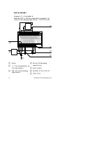
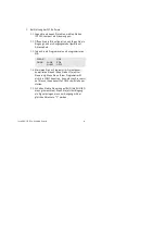
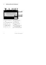
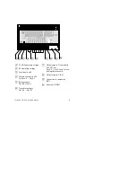
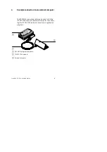
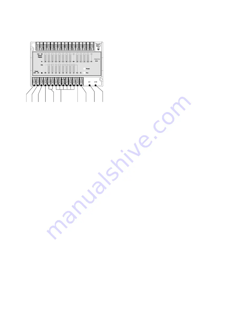
1
24 V DC operating voltage
2
0 V operating voltage
3
Functional earth
4
Common connection C0
for Out 0.0 ... Out 0.1
5
Relay outputs
Out 0.0, Out 0.1
6
Transistor outputs
Out 0.2 ... Out 0.7
7
Output supply C+ (nominally
24 V DC); for
Out 0.2 ... Out 0.7 and for con-
trolling the relay coils
8
Output supply C- (0 V)
9
Connection for extension
(EXT)
aJ
Serial port (COM)


