1. Summary of components
1−28
Festo P.BE−MPA−EN en 0802c
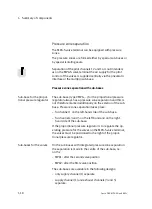
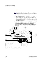
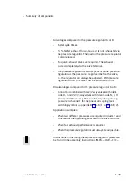
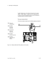
Fig.1/12 shows the following switching position of the
reversible pressure regulator B. The supply air in channel 1 is
split up:
The regulated pressure of the supply air is present in
channel 3. The pressure is regulated in front of the valve.
The unregulated pressure of the supply air from channel 1
is present in channel 5.
In the valve the regulated pressure is switched to channel 2.
The unregulated exhaust is switched in the valve from
channel 4 to channel 1 and then in the intermediate plate to
channel 3.
1
2
3
4
1
Pressure regulator
2
Valve
3
Intermediate plate
4
Sub−base
Fig.1/12: Reversible pressure regulator B
Summary of Contents for MPA-ASI Series
Page 2: ......
Page 4: ...Contents and general instructions II Festo P BE MPA EN en 0802c...
Page 8: ...Contents and general instructions VI Festo P BE MPA EN en 0802c...
Page 18: ...Contents and general instructions XVI Festo P BE MPA EN en 0802c...
Page 19: ...Summary of components 1 1 Festo P BE MPA EN en 0802c Chapter 1...
Page 55: ...Fitting 2 1 Festo P BE MPA EN en 0802c Chapter 2...
Page 71: ...Installation 3 1 Festo P BE MPA EN en 0802c Chapter 3...
Page 106: ...3 Installation 3 36 Festo P BE MPA EN en 0802c...
Page 107: ...Commissioning 4 1 Festo P BE MPA EN en 0802c Chapter 4...
Page 128: ...4 Commissioning 4 22 Festo P BE MPA EN en 0802c...
Page 129: ...Maintenance and conversion 5 1 Festo P BE MPA EN en 0802c Chapter 5...
Page 169: ...Technical appendix A 1 Festo P BE MPA EN en 0802c Appendix A...
Page 186: ...A Technical appendix A 18 Festo P BE MPA EN en 0802c...
Page 187: ...Supplementary component summary B 1 Festo P BE MPA EN en 0802c Appendix B...
Page 201: ...Index C 1 Festo P BE MPA EN en 0802c Appendix C...
Page 202: ...C Index C 2 Festo P BE MPA EN en 0802c Contents C Index C 1...

