background image

3.      Installation

3−6

Festo    P.BE−MPA−EN    en  0802c

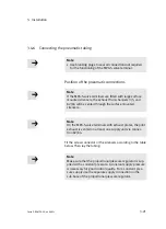
Setting  the  lubricator:

with  the  machine  running  (typical  operating  status)  0.2  to
max.  1  drop/min.  or  0.5  to  5  drops/1000  l  air.

Checking  the  setting:

the  procedure  described  below  can  be  used  for  checking  the
setting  of  the  lubricator.

Proceed  as  follows:

·

Check  the  service  units  in  respect  of  condensate  and
lubricator  setting  twice  a  week.

1. Ascertain  the  cylinder  which  is  furthest  from  the

lubricator.

2. Ascertain  the  valve  terminal  which  controls  this  cylinder.

3. Remove  the  silencer,  if  fitted,  from  connection  3/5.

4. Hold  a  piece  of  white  cardboard  10  cm  in  front  of  the

exhaust  port.

5. Let  the  system  run  for  a  short  period.

There  must  be  only  a  slight  yellow  colouring  on  the
cardboard.  If  oil  drops  out,  this  is  an  indication  that
too  much  oil  has  been  used.

Another  indication  of  over−lubrication  is  the  colouring  or  the
condition  of  the  exhaust  air  silencer.  A  distinctly  yellow
colouring  of  the  filter  element  or  drops  of  oil  on  the  silencer
indicate  that  the  lubricator  setting  is  too  high.

Summary of Contents for MPA-ASI Series

Page 1: ...Manual Pneumatic MPA S Valve terminal with MPA S pneumatics type MPA FB MPA CPI MPA MPM and MPA ASI Manual 534 241 en 0802c 688 821 MPA S valve terminal...

Page 2: ......

Page 3: ...2008 Internet http www festo com E Mail service_international festo com The reproduction distribution and utilization of this docu ment as well as the comunication of its contents to others without ex...

Page 4: ...Contents and general instructions II Festo P BE MPA EN en 0802c...

Page 5: ...nents 1 1 1 1 The MPA S valve terminal 1 4 1 1 1 Overview of variants 1 5 1 1 2 Description of components 1 9 1 1 3 Connecting and display elements 1 30 2 Fitting 2 1 2 1 General instructions on fitti...

Page 6: ...ure operation 3 19 3 4 6 Connecting the pneumatic tubing 3 21 3 4 7 Connecting the electric cables 3 25 3 5 Address assignment of the valves 3 30 3 5 1 MPA S valve terminal with CPX terminal 3 30 3 5...

Page 7: ...Replacing the sub base supply plate or MPA S end plate 5 19 5 3 7 Replacing the manifold boards 5 22 5 4 Converting the MPA S valve terminal 5 26 5 4 1 Conversion to internal or external pilot air 5 2...

Page 8: ...Contents and general instructions VI Festo P BE MPA EN en 0802c...

Page 9: ...oduct are permitted In perfect technical condition When used together with commercially available compo nents such as actuators the specified limits for pressures temperatures electrical data torques...

Page 10: ...n can be found in the separate UL specific documentation The relevant technical specifications listed there also apply here The technical specifications in this documentation may show different values...

Page 11: ...matic components and refers to the valve terminal variants listed in the following table Variants of the MPA VI valve terminal MPA S valve terminal with CPX terminal Information on CPX modules can be...

Page 12: ...on the electric electronic components see leaflet with product MPA S valve terminal with AS Interface Information on the electric electronic components see leaflet with product Tab 0 1 Connection var...

Page 13: ...agram 1 2 3 4 5 6 7 8 1 3 9 aJ 2 3 9 aJ aJ aA 1 Large surface mounted silencer or exhaust plate 2 Cover plate 3 Valves 4 Pressure sensor plate 5 Electric supply plate 6 Proportional pressure regulator...

Page 14: ...etween the following danger warnings Warning This means that failure to observe this instruction may result in serious personal injury or damage to property Caution This means that failure to observe...

Page 15: ...s tips and references to other sources of information Accessories Information on necessary or sensible accessories for the Festo product Environment Information on environment friendly use of Festo pr...

Page 16: ...pply lines tubing to the MPA S valve terminal Cover plate Plate without valve function for sealing non used valve locations on sub bases CPX module Common term for the various modules which can be inc...

Page 17: ...via the sub D plug The electric linking is constructed on a modular basis i e each sub base has its own board Multipin connection Connection with modular electric linking type MPA MPM Pneumatic inter...

Page 18: ...Contents and general instructions XVI Festo P BE MPA EN en 0802c...

Page 19: ...Summary of components 1 1 Festo P BE MPA EN en 0802c Chapter 1...

Page 20: ...onents 1 2 Festo P BE MPA EN en 0802c Contents 1 Summary of components 1 1 1 1 The MPA S valve terminal 1 4 1 1 1 Overview of variants 1 5 1 1 2 Description of components 1 9 1 1 3 Connecting and disp...

Page 21: ...the valves Connection display and operating elements Further information Instructions on connecting the electric multipin can be found in the leaflet supplied with the product Information on the modul...

Page 22: ...rating pressure and pilot pressure via the common channels and connections in the basic components The exhaust air from the valves and the pilot exhaust air is also exhausted via these common chan nel...

Page 23: ...MPA S valve terminal is available in the following grades Load voltage supply for the valves via Valve positions 1 MPA1 MPA2 CPX terminal 2 4 8 12 32 2 4 6 16 CPX terminal and electric supply plate MP...

Page 24: ...r the valves via Valve positions 1 MPA1 MPA2 CPI module 2 4 8 12 2 4 6 12 CPI terminal and electric supply plate MPA 3 4 8 12 16 2 4 6 16 1 Two solenoid coils can be controlled per valve location 2 Ma...

Page 25: ...lable in the following grades Number of valve locations 1 MPA1 MPA2 4 8 12 24 2 4 6 24 1 Max 24 valve coils can be actuated The valve coils are connected electrically at a central point via the multip...

Page 26: ...ASI 4E4A Z 2 4 2 4 VPMA ASI 8E8A Z 3 4 8 2 4 6 8 1 The max number of valve positions which can be controlled depends on the electronic module VMPA1 MPM EMM 8 and VMPA2 MPM EMM 4 occupy 2 addresses pe...

Page 27: ...sensor plate optional 2 Only with MPA S valve terminal with CPX terminal Proportional pressure regulator optional 3 Right hand end plate 4 Pneumatic supply plate optional 5 Identification labels with...

Page 28: ...2 3 1 4 3 4 2 1 Exhaust plate 3 5 or large surface mounted silencer 2 Electronic module with LEDs 3 Valve or cover plates 4 Pressure regulator plate optional Fig 1 6 Pneumatic components of the MPA S...

Page 29: ...matic components 2 5 3 4 1 4 1 Right hand end plate 2 Pneumatic supply plate optional 3 Identification labels with support optional 4 Sub base with work connections and electric linking 5 Seal optiona...

Page 30: ...4 3 4 2 1 1 Exhaust plate 3 5 or large surface mounted silencer 2 Electronic module with LEDs 3 Valve or cover plates 4 Pressure regulator plate optional Fig 1 8 Pneumatic components of the MPA S valv...

Page 31: ...e 2 Electric part of the pneumatic interface 3 Further optional CPX modules 4 Left hand end plate CPX 0 1 2 3 4 5 6 7 8 DI PS PL SF M RUN STOP ERR TP 1 2 3 4 Fig 1 9 Electric components of the MPA S v...

Page 32: ...e equipment fitted on your MPA S valve terminal Ident code Valve B 5 3 way valve open in mid position D Two single solenoid 2 2 way valves normally closed E 5 3 way valve mid position exhausted G 5 3...

Page 33: ...ssure proportional to a specified setpoint value An integrated pressure sensor records the pressure at the work connection and compares this with the setpoint value If the actual value differs from th...

Page 34: ...output pressure 1 accuracy QD 0 2 bar output pressure QE 0 6 bar output pressure QF 0 10 bar output pressure Tab 1 6 Identification code of the proportional pressure regulator Pressure sensor plate T...

Page 35: ...ics Manual CPX I O modules from Festo Pneumatic supply plate You can supply the valves with operating pressure separately via the pneumatic supply plate This is for example necessary in the case of va...

Page 36: ...e separation and this is not therefore marked additionally on the exterior of the sub base Pressure zone separation takes place for channel 1 on the left hand side of the sub base for channels 3 and 5...

Page 37: ...cer tain with which sub base variant your valve terminal is equipped see Tab 1 7 Sub base design MPA1 MPA2 Sub base with separate supply channel 1 Type VMPA AP 4 1 T1 Type VMPA AP 2 2 T0 Sub base with...

Page 38: ...th the isolating seals see also Tab 1 8 only the supply channel 1 the supply channel 1 and exhaust channels 3 and 5 only the exhaust channels 3 and 5 You can recognize whether your MPA S valve termina...

Page 39: ...thout identification Seal with open channels 1 3 and 5 7 Isolating seal channels 3 and 5 blocked Ident code R 4 Isolating seal channels 3 and 5 blocked Ident code S 8 Isolating seal channel 1 bocked I...

Page 40: ...or a 5 3 way mid position valve Alternative Cover plate for sealing an unused valve location type MPA Pressure regulator plate type VMPA B8 R C2 C with or without pressure gauge The Tab 1 10 provides...

Page 41: ...pressure 6 bar X X PN Pressure regulator plate B for connection 2 input pressure 6 bar reversible X PM Pressure regulator plate A for connection 4 input pressure 6 bar reversible X PA Pressure regulat...

Page 42: ...ted pressure of the work air exhaust ducted via the intermediate plate Pressure regulator P in channels 2 and 4 from channel 2 to channel 3 and from channel 4 to channel 5 Tab 1 11 Pressure regulator...

Page 43: ...vant exhaust channel in the valve see 2 in Tab 1 12 Exhausting During exhausting the air is passed unregulated through the valve and the pressure regulator see 3 in Tab 1 12 Pressure regulator Pressur...

Page 44: ...on 2 of the sub base The exhaust is passed unregulated via channel 4 through the intermediate plate to the valve where it is passed to channel 5 and vented 1 2 3 4 1 Pressure regulator 2 Valve 3 Inter...

Page 45: ...e 2 in Tab 1 13 the unregulated pressure from channel 1 is present The regulated air is then switched to the relevant work channel The valve is thus operated in reversible mode Exhausting In the valve...

Page 46: ...channel 3 The pressure is regulated in front of the valve The unregulated pressure of the supply air from channel 1 is present in channel 5 In the valve the regulated pressure is switched to channel...

Page 47: ...e regulator A or B the valve must be switched for this Disadvantages compared to the pressure regulator A or B Cannot be combined with 2x2 2 way valves with Ident code D I and 2x3 2 way valves with Id...

Page 48: ...exhaust connection 3 5 Valves 4 Work connections 2 4 per valve 5 Connection Pilot exhaust 82 84 only with variant for ducted exhaust 6 Supply connections Operating pressure 1 7 Pressure output 2 of t...

Page 49: ...usting knob for pressure regulator plate MPA2 with free wheeling and snap in locking Fig 1 14 Operating and connecting elements of the pressure regulator plates Information on the electric connecting...

Page 50: ...minal LEDs of the pressure sensor see Fig 1 16 3 LEDs on the valve on the MPA1 a dual colour LED valve on the MPA2 two LEDs valve yellow signal status display of the pilot solenoids red fault display...

Page 51: ...manual see System Manual for your CPX terminal table Manuals on the CPX terminal Pressure sensor plate The pressure sensor plate has the following display elements 1 Pressure sensor plate 2 Red LED pr...

Page 52: ...0802c Proportional pressure regulator The proportional pressure regulator has the following display elements 1 Green power LED 2 Proportional pressure regulator 3 Red fault LED 1 2 3 Fig 1 17 Display...

Page 53: ...following electric connecting elements on the multipin connection of the MPA S valve terminal 1 Sub D multipin plug with cable 2 Connection for functional earth 3 Sub D connection 1 2 3 Fig 1 18 Elec...

Page 54: ...llow LEDs Signal status display of the pilot solenoids 2 MPA2 yellow LEDs Signal status display of the pilot solenoids 3 Label supports with inscription field 1 2 3 Fig 1 19 Electric display elements...

Page 55: ...Fitting 2 1 Festo P BE MPA EN en 0802c Chapter 2...

Page 56: ...tructions on fitting and dismantling 2 4 2 2 Fitting variants 2 5 2 2 1 Fitting onto removing from a hat rail 2 6 2 2 2 Fitting onto removing from a hat rail 2 11 2 3 Fitting removing the inscription...

Page 57: ...on labels The manual override caps Further information Special information on replacing or adding pneumatic components can be found in chapter 5 MPA S valve terminal with CPX terminal Information on f...

Page 58: ...human beings and or damage to property Before carrying out installation and maintenance work switch off the following the compressed air supply the operating and load voltage supplies Note Handle all...

Page 59: ...mounting The multipin sub base or the pneumatic interface and the end plates contain holes for fitting the terminal onto a wall With MPA S valve terminals which are longer than 280 mm additional faste...

Page 60: ...em In this case use the wall fitting Observe the permissible values for vibration and shock in appendix A Technicalspecifications Caution A hat rail fitting without a hat rail clamping unit is not per...

Page 61: ...amping units In the right hand end plate and in the multipin sub base each with an M4 screw 1 Tab 2 2 Necessary fastening points for the hat rail fitting Fitting Proceed as follows 1 Make sure that th...

Page 62: ...rminal onto the hat rail see Fig 2 1 arrow B Make sure that the clamping element lies horizontally to the hat rail 1 H rail 2 Locking screw of the hat rail clamping unit 3 Clamping element of the hat...

Page 63: ...valve terminal with CPX terminal can be found in the CPX system manual Dismantling Proceed as follows 1 Loosen the locking screw of the hat rail clamping unit position of the screws see Tab 2 2 Make...

Page 64: ...2 Fitting 2 10 Festo P BE MPA EN en 0802c 1 H rail 2 Locking screw of the hat rail clamping unit 3 Clamping element of the hat rail clamping unit 1 A B 2 3 Fig 2 3 Dismantling the MPA S valve terminal...

Page 65: ...nal vibrations can cause damage Observe the instructions in appendix A Tab A 2 for additionally fastening the MPA S valve terminals if these are longer than 280 mm In these cases use the additional fa...

Page 66: ...one M6 screw 3 Note If your MPA S valve terminal is fitted with four or more CPX manifold sub bases fastening clips type CPX BG RW must be used as additional fastenings see system manual for the CPX t...

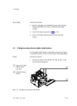
Page 67: ...A S valve terminal from the fastening surface 2 3 Fitting removing the inscription label holders An inscription label holder can be fitted onto each sub base to enable the valves or work connections t...

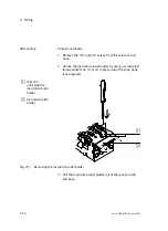
Page 68: ...base 2 Unlock the inscription label holder by using a screwdriver blade width max 3 5 mm to press down the snap hook see diagram 1 Holes for unlocking the inscription label holder 2 Inscription label...

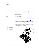
Page 69: ...1 Make sure that the relevant manual overrides are in a non actuated state If necessary set locking manual overrides to the basic position see chapter 4 Tab 4 5 2 Place the cap on the manual override...

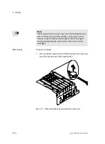
Page 70: ...ride and are constructed so that they can only be removed with a great deal of strength During dismantling the snap hooks of the cover will be damaged Dismantling Proceed as follows Use a suitable scr...

Page 71: ...Installation 3 1 Festo P BE MPA EN en 0802c Chapter 3...

Page 72: ...lve solenoid coils pilot air 3 12 3 4 2 MPA S valve terminal with pressure zone separation 3 13 3 4 3 Operation of the MPA S valve terminal with reversible pressure regulators 3 16 3 4 4 Setting the p...

Page 73: ...nts of the MPA S valve terminal with multipin connection can be found in the leaflet supplied with the product Requirements for observing the certified UL conditions if the product is operated in the...

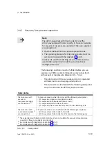
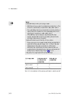
Page 74: ...re used oils with synthetic ester or true ester basis e g rape oil methylester the residual oil content must not exceed 0 1 mg m3 see ISO 8573 1 class 2 If mineral oils are used e g HLP oils as per DI...

Page 75: ...cated compressed air must be used The compressed air prepared with the compressor must correspond in quality to non lubricated compressed air If possible do not operate the complete system with lubric...

Page 76: ...urthest from the lubricator 2 Ascertain the valve terminal which controls this cylinder 3 Remove the silencer if fitted from connection 3 5 4 Hold a piece of white cardboard 10 cm in front of the exha...

Page 77: ...lowing if the UL requirements are to be complied with in your application Rules for observing the UL certification can be found in the separate UL specific documentation The relevant technical specifi...

Page 78: ...erminal The back pressures can lead to other valves being pressurized especially non switched 3 2 way valves which are closed in the normal position Avoiding back pressures Optimize the exhaust peform...

Page 79: ...of clarity group the tubing together with tube straps or multiple hose holders 1 2 Fig 3 1 Fitting the tubing Disconnecting Proceed as follows Warning If the pneumatic tubing is under pressure when c...

Page 80: ...ocking ring of the screw connector 1 e g with a screwdriver or the loosening tool QSO from Festo or loosen the locking screw 2 of the screw connector 3 Remove the tubing from the screw connector 4 Sea...

Page 81: ...be supplied via more than one supply and exhaust line when more than 6 valves of size MPA1 or more than 3 valves of size MPA2 are switched simultaneously to flow Connections on the following componen...

Page 82: ...d Tab 3 1 Recogniton features of the pilot control variants Internal pilot air supply If the operating pressure lies between 3 8 bar you can operate the pilot control of the valve solenoid coils with...

Page 83: ...rrespond to the operating pressure at which these valves are operated see diagrams in appendix A Fig A 1 and Fig A 2 3 4 2 MPA S valve terminal with pressure zone separation The pressure zones are for...

Page 84: ...en 3 8 bar If the proportional pressure regulator is to regulate the oper ating pressure for the valves on the MPA S valve terminal the valves must be positioned to the right of the proportional press...

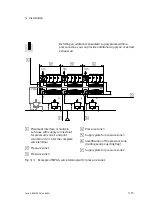
Page 85: ...3 5 3 5 1 Pneumatic interface or multipin sub base with supply connection 1 for presssure zone 1 and pilot connection 12 14 for the complete valve terminal 2 Pressure zone 1 3 Pressure zone 2 4 Pressu...

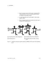
Page 86: ...ble valves may be operated with these pressure regulators 3 4 4 Setting the pressure regulator The pressure regulator plates can be set with the following operating elements with size MPA1 via the adj...

Page 87: ...e adjusting knob at right angles to the pressure regulator plate 5 Press the adjusting knob in this position into the snap in locking of the locking level 1 2 1 3 4 1 2 3 4 5 1 1 Adjusting knob in the...

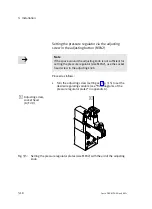
Page 88: ...for setting the pressure regulator size MPA2 use the socket head screw in the adjusting knob Proceed as follows Turn the adjusting screw setting see Fig 3 5 to set the desired regulating variable see...

Page 89: ...rnal closed loop regulated pilot air The valve terminal is fitted with the following valve plates and in some cases has further pressure zones Valve plates Pressure zone with vacuum or low pressuresup...

Page 90: ...valve in a separate pressure zone with separate exhaust channel 5 Valve with Ident code W and X 3 2 way valve These valves can be supplied individually and therefore operated in the pressure range 0 9...

Page 91: ...ill be vented through the surface mounted silencers Note On the MPA S valve terminals with exhaust plates the pilot exhaust is vented on at least one supply unit via connec tion 82 84 Fit the screw co...

Page 92: ...3 Installation 3 22 Festo P BE MPA EN en 0802c 1 2 4 82 84 12 14 3 5 1 3 5 4 2 1 3 P1 2 Fig 3 6 Pneumatic connections of the MPA S valve terminal...

Page 93: ...rew connector in the supply plate 2 Work air or vacuum 2 or 4 MPA1 M7 MPA2 G Screw connector in the sub base Connection for external pressure P1 M7 Screw connector in pressure sensor plate type VMPA F...

Page 94: ...t air Use non return valves in the common exhaust lines 3 5 or 82 84 in order to prevent functional impairment due to back pressures 1 First MPA S valve terminal 2 Common 3 5 3 Central 82 84 4 Central...

Page 95: ...al requirements Note Check within the framework of your EMERGENCY STOP circuit to ascertain the measures necessary for putting your machine system into a safe state in the event of an EMERGENCY STOP e...

Page 96: ...e load voltage that only the electronic modules with electrical isolation type VMPA FB EMG are permitted to the right of the electric supply plate see also section 5 3 5 If your MPA S valve terminal i...

Page 97: ...Plug 7 8 4 pin Pin assignment D C Pin A n c D C Pin B 24 V DC valves Pin C FE A B Pin D 0 V DC valves Tab 3 6 Pin assignment of the electric supply plate type VMPA FB SP 7 8 V 4POL Plug 7 8 5 pin Pin...

Page 98: ...multipin sub base see fig at low impedance short cable with large cross sectional area with the earth potential Please note the supplementary instructions on the MPA S valve terminals with CPX termina...

Page 99: ...en 0802c 1 1 MPA S valve terminal with multipin connection MPA S valve terminal with CPX terminal MPA S valve terminal with CPI module 1 MPA S valve terminal with AS Interface 1 1 Earth connection Fig...

Page 100: ...maximum 32 valve locations Note Note with the addressing that an MPA2 pneumatic module has only 4 addresses compared to an MPA1 pneumatic module Assigning the addresses The assignment of the addresses...

Page 101: ...es MPA2 5 Pneumatic modules MPA1 6 Addresses of valve coils 14 7 Addresses of valve coils 12 Fig 3 9 Example Address assignment of an MPA S valve terminal with CPX terminal and 6 valve locations top v...

Page 102: ...assignment does not depend on whether blanking plates or valve plates are fitted Depending on the electronic module a valve location occupies the following number of addresses Number of dd Electronic...

Page 103: ...nded at a later stage In the following example an MPA S valve terminal type MPA MPM PI with the folllowing components is addressed Component MPA1 MPA2 Sub bases 2 8 valve positions 2 4 valve positions...

Page 104: ...MPM EMM 2 for 2 MPA2 valves 10 9 5 14 for 2 MPA2 valves each with one coil 11 10 6 14 VMPA1 MPM EMM 4 for 4 MPA1 valves 12 11 7 14 for 4 MPA1 valves each with one coil 13 12 8 14 14 13 9 14 15 16 14...

Page 105: ...Sub base with electronic module VMPA2 MPM EMM 4 occupies two addresses per valve location 7 Supply plate for additional pressure supply 8 Sub base with electronic module VMPA1 MPM EMM 4 occupies one a...

Page 106: ...3 Installation 3 36 Festo P BE MPA EN en 0802c...

Page 107: ...Commissioning 4 1 Festo P BE MPA EN en 0802c Chapter 4...

Page 108: ...pply 4 4 4 2 Manual override 4 6 4 3 Checking the valves and the valve actuator combination 4 8 4 4 LED display of the valves 4 13 4 5 LED display of the proportional pressure regulator 4 16 4 6 Commi...

Page 109: ...e supply Operating the manual overrides Checking the valves and the valve actuator combination The assignment of LEDs and manual overrides to the valve solenoid coils Function impairments Operating st...

Page 110: ...e constantly under stress Please observe the following instructions on building up pressure in the complete supply 4 1 2 Pressure increase in the complete supply Warning If the build up in pressure of...

Page 111: ...being pres ent The slow increase in pressure of the complete supply does not then affect the actuator The actuator would react suddenly e g a cylinder would extend or retract suddenly depending on the...

Page 112: ...1 Effects of slow start up pressurization 4 2 Manual override You should use the manual override especially when commis sioning the pneumatic system in order to check the function and operation of th...

Page 113: ...if a cap is fitted The assignment of the manual override actuations to the valve solenoid coils is as follows 1 2 12 12 12 12 14 14 14 14 14 14 14 14 12 14 14 1 2 2 3 4 1 Manual override for valve so...

Page 114: ...ssioning variants Activity Preliminarytest of the pneumatictubing Test the valve actuator combination by means of the manual override Complete commissioning of the complete system Installing and conne...

Page 115: ...ing commissioning manual override functions which are in the switched state can cause actuators to perform sudden unexpected movements These movements can cause injury to human beings and damage to pr...

Page 116: ...th only max 25 N 3 With the locking function of the manual override After testing the valves make sure that all manual override actuations are in their basic positions again Caution Valves with manual...

Page 117: ...ual overrides without a cap do not turn the pressed down plunger as otherwise the manual override will lock The valve moves to the switching position Keep the plunger of the manual override pressed do...

Page 118: ...press down the plunger of the manual override until the valve switches Then turn the plunger in a clock wise direction as far as possible The valve moves to the switching position Leave the plunger in...

Page 119: ...ws the position of the LEDs and the manual overrides for the relevant valve solenoid coil 2 1 2 1 2 1 3 4 12 12 12 12 14 14 14 14 14 14 14 14 12 14 14 1 LED and manual override for valve solenoid coil...

Page 120: ...on Logical 1 signal present Logical 1 but compressed air supply not OK or pilot exhaust blocked or servicingrequired lights up red In the starting phase for approx 2 seconds Duringoperation test phase...

Page 121: ...ition of the valve Meaning out Basic position Logical 0 no signal yellow alight Switch position or Basic position Logical 1 signal present Logical 1 but load voltage of the valves lies below the permi...

Page 122: ...ult LED red lights up out Normal operating status lights up lights up Non permitted nominal value Non permitted parameter There is a hardware fault Internal temperature too high lights up flashes Ther...

Page 123: ...io sets mobile telephones or other devices which cause interference In this way you will avoid increased toler ances in the output pressure compare specifications on EMC in appendix A The proportional...

Page 124: ...10 bar type 0 1 bar 10 bar 1 FS Full scale 1 FS 0 1 V 100 FS 10 V 2 0 V 0 bar Tab 4 9 Output signal of the proportional pressure regulator Further important Information on commissioning the proportion...

Page 125: ...eck the tubing fitting The valve or the pneumatic system does not react as expected does not react Check the tubing Check the electric cables Bring the locking manual override into the basic position...

Page 126: ...hed Modify nominal value Proportional pressure regulator defective Send the device to Festo for repairs Flow too low Restriction of the flow cross section due to connection design swivel fitting conne...

Page 127: ...centrally ducted exhaust are used Two or more pressure zones Limiting the pressure zones by means of isolating seals with blocked channels Appropriate number of pneumatic supply plates for the variou...

Page 128: ...4 Commissioning 4 22 Festo P BE MPA EN en 0802c...

Page 129: ...Maintenance and conversion 5 1 Festo P BE MPA EN en 0802c Chapter 5...

Page 130: ...alves or cover plates 5 8 5 3 4 Replace the proportional pressure regulator 5 11 5 3 5 Replacing electronic modules 5 12 5 3 6 Replacing the sub base supply plate or MPA S end plate 5 19 5 3 7 Replaci...

Page 131: ...e supply plate and end plate The following activities are also described Adding pressure zones Converting the valve terminal to internal or external pilot air Further information MPA S valve terminal...

Page 132: ...g and load voltage supplies Note Handle all modules and components of the MPA S valve terminal with great care Note especially the following when fitting components Screws must be fitted accurately ot...

Page 133: ...d silencer Loosen the electrical connections Connecting variants Procedure CPX terminal Instructions on loosening the electrical connections can be found in the CPX system manual Multipinconnection Lo...

Page 134: ...the safety regulations for handling easily inflammable cleaning agents In this way you can ensure that the large surface mounted silencer functions correctly and that the valves operate correctly Pro...

Page 135: ...eal between the basis component and the surface mounted silencer or exhaust plate for damage Replace the seal if it is damaged 3 Make sure that the seal is seated correctly The seating is determined b...

Page 136: ...th multipin connection support the control of one or two solenoid coils per valve location depending on the MPA electronic module fitted see Tab 5 4 Dismantling Proceed as follows Use a screwdriver wi...

Page 137: ...f they are damaged 3 Make sure that the cord seal is seated correctly between the sub base and the components The cord seal must lie in the recess for the components 1 Fastening screws of the valve or...

Page 138: ...the component 2 Valve or cover plate 3 Cord seal 4 Sub base 5 Electronic module Fig 5 3 Fitting valve plates or blanking plates MPA2 4 Place the component on the sub base 5 Screw the component at firs...

Page 139: ...scribed in the mounting instructions VMPA 6TA 1 Proportional pressure regulator 2 Fastening screws of the proportional pressure regulator tightening torque 1 80 2 20 Nm 3 Sub base 4 Fastening screws o...

Page 140: ...4 valve locations for size MPA2 contacts for 2 valve locations The LEDs function see chapter 4 and further electronic components are integral parts of the electronic module Caution The electronic mod...

Page 141: ...MPA1 FB EMS or VMPA2 FB EMS you must supply the MPA pneumatcs exclusuvely via a 4 pin system supply module type CPX GE EV S or CPX GE EV S 7 8 4POL Note the overview in Tab 5 2 Note that MPA electroni...

Page 142: ...CPX GE EV V system supply 7 8 5 pin type CPX GE EV S 7 8 5POL electric supply plate MPA type VMPA FB SP V Note The electrical function of an MPA pneumatic module is determined by the electronic modul...

Page 143: ...2 VMPA2 FB EMG 4 2 valve locations 4 outputs withelectrical isolation VMPA2 FB EMG D2 4 2 valve locations 4 outputs withelectrical isolation with diagnostic functions D2 VMPA2 FB VMPA2 FB EMS 4 2 valv...

Page 144: ...noid coils 1 Control of twovalve coils is supported per valve location 2 Control of one valve coil is supported per valve location Tab 5 4 Electronic modules for the MPA S valve terminal with multipin...

Page 145: ...te 2 Valve or cover plates 3 Cord seal 4 Electronic module 5 Sub base 6 Inscription label holder 7 Seal of the electronic module 8 Fastening screws of the electronic module 9 2 conical ring seals per...

Page 146: ...nd damage to the electrical contacts Note Before fitting check the condition and position of the followingseals seal of the electronic module the ring seal of the electrical contacts the cord seal of...

Page 147: ...e section 5 2 2 Place the MPA S valve terminal on a flat working surface 3 Loosen the screws of the component sub base supply plate or end plate which you wish to remove in the sequence 3 2 1 see diag...

Page 148: ...as follows 1 Make sure the seals are not damaged Replace the seals if they are damaged 2 Place the sheet metal seal onto the guide pins of the sub base or supply plate 1 Guide pins 2 Seal optional iso...

Page 149: ...gram by hand Then tighten the screws with a torque of 1 62 1 98 Nm 1 2 2 1 3 Fig 5 8 Screw connectors of the sub bases 4 Fit the MPA S valve terminal onto the fastening surface see chapter 2 Fitting o...

Page 150: ...MPA S valve terminal with multipin connection Manifold boards for Version one sub base one sub base and a supply plate Type VMPA1 MPM EV AB 8 Type VMPA1 MPM EV ABV 8 Only for size MPA1 Board for contr...

Page 151: ...3 5 3 Loosen the sub base from the neighbouring components see section 5 3 6 4 If you wish to remove the last manifold board in front of the right hand MPA end plate you must remove the end piece typ...

Page 152: ...Fitting Proceed as follows 1 Push the manifold board to be fitted into the sub base from the right until it clips into position Fig 5 11 Fitting the manifold board 2 If the fitted manifold board is th...

Page 153: ...PA 1 Fig 5 12 Fitting the end piece into the last manifold board 3 Fit the sub base to the neighbouring components see section 5 3 6 4 Fit the electronic module into the sub base see section 5 3 5 5 F...

Page 154: ...of the MPA S valve terminal to internal or external pilot air Conversion of the MPA S valve terminal to different pressure zones Adding valve locations sub bases 5 4 1 Conversion to internal or extern...

Page 155: ...usting via large surface mounted silencer VMPA FB EPL GU MPA1 MP EPL GU VMPA1 MPM EPL GU Sealed connection 12 14 Large surface mounted silencer Operation with external pilot air Ducted exhaust air VMP...

Page 156: ...astening surface see this chapter Dismantling the MPA S valve terminal 2 Place the MPA S valve terminal on a flat working surface 3 Loosen the fastening screws between the multipin sub base and the pn...

Page 157: ...the seals if they are damaged 2 Place the seal onto the guide pins of the multipin sub base 1 Multipin sub base 2 Guide pins 3 Seal 4 Pneumatic sub base 2 1 2 3 4 Fig 5 14 Fitting the multipin sub ba...

Page 158: ...1 2 3 as shown in the diagram at first slightly and then with 1 3 Nm 2 1 3 Fig 5 15 Screw connectors of the sub bases 5 Fit the MPA S valve terminal onto the fastening surface see chapter 2 Fitting o...

Page 159: ...ly of the valves via the electric supply plate Tab 5 7 Number of pressure zones The pressure zones are formed either by special sub bases or by special isolating seals see chapter 1 section Pressure z...

Page 160: ...atic supply plate MPA S valve terminal with multipin connection an appropriately lengthened manifold board see section Overview of the manifold boards MPA S valve terminal with CPX terminal for the pn...

Page 161: ...e terminal with multipin connection In order to bridge the pneumatic supply plate replace the short manifold board in the sub base which follows the pneumatic supply plate by a longer version see sect...

Page 162: ...d pressure zone 3 Valve plates of the 3rd pressure zone 4 Supply plate with connection 1 for supplying compressed air to the 3rd pressure zone 5 Marking the isolating seal with pressure zone separatio...

Page 163: ...als the maximum number of solenoid coils which can be actuated by the multipin connection is limited to 24 addresses If control is carried out with size MPA 1 or MPA 2 and valves with the same number...

Page 164: ...positions VMPA1 FB AP VMPA2 FB AP One electronic module per sub base VMPA FB EM VMPA MPM EMM Valve or cover plates MPA1 4 per sub base MPA2 2 per sub base VMPA M1H VMPA M1H If necessary additional pne...

Page 165: ...PRS Tab 5 10 Valve location extension Dismantling Proceed as follows 1 Loosen the MPA S valve terminal from the fastening surface see section Dismantling the MPA S valve terminal 2 Remove the sub bas...

Page 166: ...valve plates or blanking plates onto the empty valve locations see section 5 3 3 4 Mount the MPA S valve terminal on the fastening surface see chapter 2 Fitting onto a wall or Fitting onto a hat rail...

Page 167: ...c and pneumatic connections and remove the MPA S valve terminal from its fastening surface see section 5 2 2 Fit the electric supply plate in accordance with the specifi cations in the mounting instru...

Page 168: ...y components For extension you will require Components Type Proportional pressure regulator VPPM 6TA L 1 0L Electronic module Sub base Also asealwithoutchannelseparat oranisolatingsealwithchannelsepar...

Page 169: ...Technical appendix A 1 Festo P BE MPA EN en 0802c Appendix A...

Page 170: ...A Technical appendix A 2 Festo P BE MPA EN en 0802c Contents A Technical appendix A 1 A 1 Technical specifications A 3 A 2 Festo accessories A 17...

Page 171: ...emblyposition as desired with hat rail fitting only horizontal Tightening torques MA Electronic modules on sub bases Proportional pressure regulator on sub base Exhaust plates on pneumatic supply plat...

Page 172: ...ted silenecer Per sub base with seal electronic module electric linking label supports screws Per pneumatic supply plate with seal electric linking screws exhaust plate large surface mounted silencer...

Page 173: ...which can be actuated is limited by the multipin connection to 24 addresses MPA S valve terminal with CPX terminal Maximum 16 sub bases MPA S with electric supply plate or 8 sub bases MPA S without e...

Page 174: ...ngth of 280 mm between the pneumatic interface and the right hand end plate with additional fastening on the pneumatic supply plates Severity level 2 3 MPA S valve terminal with CPI with AS Interface...

Page 175: ...bar Valve location Ident code W at connection 2 0 9 10 bar Valve location Ident code X at connection 4 0 9 10 bar Valve location Ident code D H I K and N at connection 1 3 10 bar All valve plates at...

Page 176: ...related to the operating pressure with external pilot air supply and use of valve plates with Ident code D H I K and N 1 Pressure of the external pilot air supply at pilot connection 12 14 bar 2 Work...

Page 177: ...rised 5 3 way closed 5 3 way exhausted 230 260 300 230 300 255 360 300 220 3 320 240 230 260 300 310 305 295 360 270 320 240 200 3 Valve switching times in ms Measuring method 0 10 as per FN 942032 On...

Page 178: ...50 350 3 630 440 350 3 650 550 500 550 470 670 510 610 590 480 540 480 560 670 600 350 3 610 420 350 3 Valve switching times in ms Measuring method 0 10 as per FN 942032 On changeover Off D I N K H X...

Page 179: ...tput pressure 2 Flow rate 1 2 Fig A 3 Diagram Flow as a factor of the output pressure for the proportional pressure regulator P size MPA2 Ident code PF and PA Pressure regulator B 1 Output pressure 2...

Page 180: ...Fig A 5 Diagram Flow as a factor of the output pressure for the pressure regulator A size MPA2 Ident code PG and PB Reversible pressure regulator B 1 Output pressure 2 Flow rate 1 2 Fig A 6 Diagram Fl...

Page 181: ...13 Festo P BE MPA EN en 0802c Reversible pressure regulator A 1 Output pressure 2 Flow rate 1 2 Fig A 7 Diagram Flow as a factor of the output pressure for the reversible pressure regulator A size MPA...

Page 182: ...PA EN en 0802c Flow curves for type VPPM 6TA L 1 2 bar valve variant type VPPM 6TA L 1 OL2H 6 bar valve variant type VPPM 6TA L 1 OL2H 10 bar valve variant type VPPM 6TA L 1 OL2H Tab A 7 Flow curves o...

Page 183: ...m Tab A 8 Technical specifications for the electric components general Electrics MPA S valve terminal with multipin connection or AS Interface Voltage supply Nominalvoltage Residual ripple 24 V DC 25...

Page 184: ...urrent consumption per solenoid coil out of load voltage VVAL at 24 V MPA1 MPA2 Nominalpullcurrent duration Nominal current with current reduction 58 mA 20 ms 9 mA after 20 ms 99 mA 20 ms 18 mA after...

Page 185: ...nual override cover manual override not accessible Manual override cap manual override can only be operated in non lockingmode Inscription label holder Additional fastening bracket for wall fitting B...

Page 186: ...A Technical appendix A 18 Festo P BE MPA EN en 0802c...

Page 187: ...Supplementary component summary B 1 Festo P BE MPA EN en 0802c Appendix B...

Page 188: ...ary component summary B 2 Festo P BE MPA EN en 0802c Contents B Supplementary component summary B 1 B 1 Overview of valve location components B 3 B 2 Separating the MPA S valve terminal from the CPX t...

Page 189: ...ions coils and manual overrides e g designation 14 stands for manual override 14 or coil 14 They are not logic designations Note Address assignment of the MPA S valve terminal with multipin connection...

Page 190: ...ection 4 with valve coil 12 operating pressure is switched from connection 1 to connection 2 With vacuum operation supply operating pressure via connection 1 supplyvacuum via connection 5 with valve c...

Page 191: ...1 4 2 12 14 Ident code K Function Two single solenoid 3 2 way valves Normally closed Springreturn 82 84 12 14 5 3 1 4 2 12 14 Ident code N Function Two single solenoid 3 2 way valves Normallyopen Spri...

Page 192: ...MPA EN en 0802c 5 2 way valves 82 84 12 14 5 3 1 4 2 12 14 Ident code J Function One 5 2 way double solenoid valve Double solenoid 82 84 12 14 5 3 1 4 2 14 Ident code M Function One single solenoid 5...

Page 193: ...5 3 way valves are energized simultaneously the valve remains in the switch position 5 3 way valves 82 84 12 14 5 3 1 4 2 12 14 Ident code B Function 5 3 way valve Open in mid position 82 84 12 14 5 3...

Page 194: ...n channel 1 in front of the directional control valve 2 4 14 5 1 3 12 Pressure regulator plate for connection 2 pressure regulator B Ident code PH or PC Function Regulates the operating pressure in ch...

Page 195: ...alve Note Cannot be combined with 2x2 2 way valves Ident code D and I and 2x3 2 way valves Ident code H K and N 2 4 14 5 1 3 12 Pressure regulator plate for connection 4 reversible pressure regulator...

Page 196: ...ry B 10 Festo P BE MPA EN en 0802c Proportional pressure regulator VPPM 6TA w w 3 1 2 x Ident code QA QB QC QD QE QF Function Regulates the pressure proportional to a specified nominal value Tab B 6 P...

Page 197: ...1 CPX terminal 2 Pneumatic interface 3 MPA S valve terminal 1 2 3 Fig B 1 Pneumatic interface Dismantling Proceed as follows 1 Loosen the electrical and pneumatic connections and remove the MPA S valv...

Page 198: ...component summary B 12 Festo P BE MPA EN en 0802c 2 1 3 Fig B 2 Removing the MPA S valve terminal from the pneumatic interface Information on replacing the pneumatic interface can be found in the CPX...

Page 199: ...are damaged 2 Place the seal onto the guide pins of the pneumatic interface 1 Guide pins 2 Pneumatic sub bases 3 Seal 4 Pneumatic interface 1 2 3 4 1 Fig B 3 Fitting the MPA S valve terminal to the p...

Page 200: ...62 1 98 Nm 2 1 3 Fig B 4 Fastening the MPA S valve terminal to the pneumatic interface 5 Fasten the MPA S valve terminal onto the fastening surface see CPX system manual 6 Complete the electrical and...

Page 201: ...Index C 1 Festo P BE MPA EN en 0802c Appendix C...

Page 202: ...C Index C 2 Festo P BE MPA EN en 0802c Contents C Index C 1...

Page 203: ...th multipin plug connection 3 32 Outputs 3 30 Air humidity Permitted A 3 Approvals VII AS Interface X 1 8 C CE identification VII Cleaning Large surface mounted silencer 5 6 Common tubing 3 24 Compone...

Page 204: ...lements 1 32 1 35 1 36 E Electric supply plate Connecting the load voltage 3 26 Electromagnetic compatibility A 15 Electronic module Dismantle fit 5 12 EMERGENCY STOP 4 21 End plate Dismantle fit 5 19...

Page 205: ...Position of the LEDs 4 13 4 17 Proportional pressure regulator 4 16 Switching status display of the valve coil 4 14 4 15 Load voltage A 16 Low pressure operation 3 19 4 21 M Manifold boards Replace 5...

Page 206: ...9 1 10 1 11 1 12 Sizes 1 5 With AS Interface 1 8 With CPI module 1 6 With CPX terminal 1 5 1 32 With multipin plug connection 1 7 1 35 1 36 Multipin connection 1 7 1 13 Multipin sub base Dismantle fit...

Page 207: ...tor P 1 24 Reversible 3 16 Reversible pressure regulator A B 1 27 Set 3 16 Pressure sensor plate 5 39 Pressure zones 1 18 3 13 4 21 5 31 Seals 1 33 1 34 Proportional pressure regulator 5 40 Dismantle...

Page 208: ...m number 3 30 Valve solenoid coils Current consumption A 15 Valves 1 14 1 16 Dismantle fit 5 8 Identification code Ident code 1 14 1 16 Overview B 3 Vertical stacking 1 22 Identification in the type c...

Reviews: