background image

(de) Bedienungs−
anleitung

(en) Operating 
instructions

Durchflusssensor
Flow  sensor

MS6−SFE−...

680  023
0507NH

Summary of Contents for MS6-SFE N2I Series

Page 1: ...de Bedienungs anleitung en Operating instructions Durchflusssensor Flow sensor MS6 SFE 680 023 0507NH...

Page 2: ...alifi h l d Warnung Warning Caution Hinweis Please note Umwelt Antipollution Zubeh r Accessories q ziertem Fachpersonal gem Bedienungs anleitung Fitting and commissioning to be carried out by qualifie...

Page 3: ...r den Produkteinsatz 6 4 Einbau 8 Mechanisch 8 Pneumatisch 9 Elektrisch 10 5 Inbetriebnahme 12 Inbetriebnahme Vorbereitung 14 RUN Modus 14 SHOW Modus 15 EDIT Modus 15 TEACH Modus 18 LOCK Modus 18 REC...

Page 4: ...l sse 6 1 2 3 4 8 7 MS6 SFE F5 AGD MS6 SFE F5 5 6 1 Display 2 DOWN Taste B Taste 3 Edit Knopf 4 UP Taste A Taste 5 Siebpatrone nur bei Typ MS6 SFE F5 6 Druckluftanschluss 7 Stecker f r elektrischen An...

Page 5: ...FE F5 AGD oder den Zusammenbau mit Wartungsger ten der MS Reihe MS6 SFE F5 Bei der Messung wird ein thermisches Verfahren angewandt Hierbei wird die W rmemenge ermittelt die einer beheizten Fl che des...

Page 6: ...ufge f hrt sind Warnung Kondenswasser lnebel Fremdk rper und andere Verunreinigungen in der Druckluft k nnen das Produkt besch digen und f hren zu Messfehlern und Funktionsst rungen S Stellen Sie sich...

Page 7: ...r cksichtigen Sie die Umgebungsbedin gungen am Einsatzort S Ber cksichtigen Sie die Vorschriften der Berufsgenossenschaft des Technischen berwachungsvereins des VDE oder entsprechende nationale Bestim...

Page 8: ...hen Anschluss von mindestens 1 2 haben Beim Zusammenbau mit einem bereits vorhandenen Wartungsger t der MS Baureihe 1 Beachten Sie die Durchflussrichtung 2 Installieren Sie den MS6 SFE nur nach Wartun...

Page 9: ...trom wird an dem Anschluss zugef hrt an dem sich die Sieb patrone bei Typ MS6 SFE F5 bzw die Einlaufstrecke bei Typ MS6 SFE F5 AGD befindet Am gegen berliegenden Anschluss wird der Luftmassen strom en...

Page 10: ...n Sie auf korrekten Anschluss der Druckluftleitungen S Drehen Sie die Verschraubungen unter Verwendung von geeignetem Dicht material in die pneumatischen Anschl sse Elektrisch Warnung S Verwenden Sie...

Page 11: ...t Pin Belegung Kabelfarben 1 Stecker 1 24 V DC Versorgungsspannung Braun BN 5 polig M12 1 2 Digitalausgang B Out B Wei WH 1 3 0 V Blau BU 2 4 4 Digitalausgang A Out A Schwarz BK 5 3 5 Analogausgang C...

Page 12: ...wellwert Komparator Bei Einstellung Fenster Komparator Bei EinstellungNO Schlie er q 1 0 Hy OUT SP Hy Hy q 1 0 OUT SP Lo SP Hi Bei EinstellungNC ffner q 1 0 SP Hy OUT q 1 0 OUT SP Lo SP Hi Hy Hy Bild...

Page 13: ...n Verbrauchsmesswert zur cksetzen Schaltausgang gesetzt nicht gesetzt Schwellwert Komparator Fenster Komparator Schaltpunkt switching point Unterer Schaltpunkt switching point low Oberer Schaltpunkt s...

Page 14: ...ebnahme Vorbereitung Der Grundzustand hei t RUN Modus Er zeigt den aktuellen Messwert an Aus anderen Modi heraus erreichbar durch 3 s langes Dr cken des Edit Knopfs oder Ablauf einer berwachungszeit T...

Page 15: ...f r Out A und Out B Folgende Einstellungen werden angezeigt Bei Durchflussmessung Flow Out A B Schaltfunktion Schwellwert Fenster Komparator Schaltpunkt SP oder SP Lo und SP Hi Hysterese HY Schaltcha...

Page 16: ...erte Verbrauchs messung Out A und Durchflussmessung Out B ist m glich S Vollziehen Sie folgende Schritte a Auswahl des Schaltausgangs Schaltausgang Out A Schaltausgang Out B 1 Um den EDIT Modus zu akt...

Page 17: ...w nschte Schaltfunktion Schwell wert Fenster Komparator w hlen mitUP DOWN Taste 5 Zur Best tigung Edit Knopf dr cken 6 Schaltpunkt SP bzw SP Lo einstellen mitUP DOWN Taste 7 Zur Best tigung Edit Knopf...

Page 18: ...4 Durchfluss Flow2 erzeugen 5 Um den Wert Flow2 zu bernehmen zuerst die unter 2 gew hlte Taste dr cken dann bei gedr ckter Taste den Edit Knopf dr cken MS6 SFE ist wieder im RUN Modus Bei Einstellung...

Page 19: ...an Minimal Maximalwert anzeigen S Um MINMAX Modus zu aktivieren dr cken Sie die Tasten A und B gleichzeitig Der bis zu diesem Zeitpunkt niedrigste Durchflusswert wird angezeigt min F Lo S Dr cken Sie...

Page 20: ...R Modus zu aktivieren Edit Knopf dr cken Messung starten 5 Befehl RUN w hlen mit UP DOWN Taste RUN blinkt 6 Zur Best tigung Edit Knopf dr cken Aufzeichnung startet Lauflicht 1 Segment Ein blinkendes R...

Page 21: ...sich die zu vergleichenden Volumenstr me z B Betriebsvolumenstrom Liefermenge eines Kompressors Messwerte eines Durchflusssensors von einem anderen Hersteller auf dieselben Ausgangsbedingungen bezieh...

Page 22: ...inigungsmedien sind Seifenlauge max 60 C Waschbenzin und alle werkstoffschonenden Medien 8 Ausbau 1 Schalten Sie zum Ausbau folgende Energiequellen ab Betriebsspannung Druckluft 2 Trennen Sie die jewe...

Page 23: ...trone oder Einlaufstrecke betreiben Bei Durchfluss messung Messwert wird blinkenddargestellt Messung au erhalb des zul ssigenMessbereichs Genauigkeit bezieht sich nur auf den zul ssigen Mess bereich B...

Page 24: ...v bar Durchflussmessbereich l min 200 5 000 eingeschr nkt bei 5 bar Betriebsdruck siehe Bild 19 Umgebungstemperatur Mediumstemperatur Nenntemperatur C C C 0 50 0 50 23 Betriebsspannungsbereich Restwe...

Page 25: ...Ausgangsstrom Reststrom Kapazitive Last maximal DC mA mA nF 100 0 05 100 Schutzfunktionen Verpolungsschutz Kurzschlussfestigkeit berlastfestigkeit InduktiveSchutzbeschaltung F r alle elektrischen Ans...

Page 26: ...MS6 SFE Festo MS6 SFE 0507NH Deutsch 26 Durchflussmessbereich qn in Abh ngigkeit vom Betriebsdruck p1 qn l min p1 bar Bild 19...

Page 27: ...RUN Modus zur ckzukehren 3 SekundenEdit Knopfdr cken Durchfluss erzeugen zum Teachen des Messwertes hier Flow 1 Symbol auf dem Display blinkt hier Out B Sicherheitscode aktiv Lock Sperrung gegen unbe...

Page 28: ...MS6 SFE Festo MS6 SFE 0507NH Deutsch 28 1 2 1 Grundzustand RUN Modus 2 Weiterschalten zum LOCK Modus siehe Bild 22 Bild 21 EDIT Modus...

Page 29: ...MS6 SFE Festo MS6 SFE 0507NH Deutsch 29 1 2 Nur wenn Out A im Modus FLOW 1 Grundzustand RUN Modus 2 Einstieg vom EDIT Modus siehe Bild 21 Bild 22 LOCK Modus und RECORDER Modus...

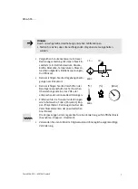
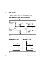
Page 30: ...MS6 SFE Festo MS6 SFE 0507NH Deutsch 30 1 1 Grundzustand RUN Modus Bild 23 SHOW Modus...

Page 31: ...MS6 SFE Festo MS6 SFE 0507NH Deutsch 31 1 1 Grundzustand RUN Modus Bild 24 MINMAX Modus und TEACH MODUS...

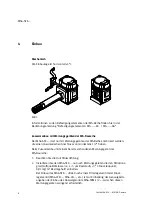
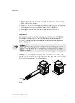
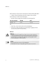
Page 32: ...MS6 SFE Festo MS6 SFE 0507NH Deutsch 32...

Page 33: ...allation 38 Mechanical installation 38 Pneumatic installation 39 Electrical installation 40 5 Commissioning 42 Preparing commissioning 44 RUN mode 44 SHOW mode 45 EDIT mode 45 TEACH mode 48 LOCK mode...

Page 34: ...6 1 2 3 4 8 7 MS6 SFE F5 AGD MS6 SFE F5 5 6 1 Display 2 DOWN button B button 3 Edit button 4 UP button A button 5 Sieve cartridge only with type MS6 SFE F5 6 Compressed air connection 7 Plug for elec...

Page 35: ...F5 AGD or combination with service units of the MS series MS6 SFE F5 Measurement is carried out by means of a thermal procedure The amount of heat which is drawn from a heated surface of the sensor b...

Page 36: ...n matter and other dirt in the compressed air can damage the product and cause incorrect measurements and functional disorders S Make sure that the following grade of filtration is reached on the supp...

Page 37: ...s flow rates S Take into consideration the ambient conditions at the location of use S Please comply with national and local safety laws and regulations S Remove all transport packing such as pro tect...

Page 38: ...which have a pneumatic connection of at least 1 2 If combined with an existing service unit of the MS series 1 Please note the direction of flow 2 Install the MS6 SFE only after service units which c...

Page 39: ...ovided at the connection where the sieve cartridge on type MS6 SFE F5 or the starting stretch on type MS6 SFE F5 AGD is situated The air mass current is taken from the connection lying opposite Please...

Page 40: ...re that the compressed air tubing is connected correctly S Screw the connectors into the pneumatic ports using suitable sealing material Electrical installation Warning S Use only power units which gu...

Page 41: ...as follows Pin Allocation Cable colours 1 Plugs 1 24 V DC power supply brown BN 5 pin M12 1 2 Digital output B Out B white WH 1 3 0 V blue BU 2 4 4 Digital output A Out A black BK 5 3 5 Analogue outpu...

Page 42: ...r Settingthewindowcomparator Setting the normallyopen contact NO q 1 0 Hy OUT SP Hy Hy q 1 0 OUT SP Lo SP Hi Setting NC normally closed q 1 0 SP Hy OUT q 1 0 OUT SP Lo SP Hi Hy Hy Fig 10 With accumula...

Page 43: ...ated consumption measurement Reset accumulated consumption measurement Switching output set not set Threshold value comparator Window comparator Switching point Lower switching point Upper switching p...

Page 44: ...F Hi will be displayed Preparing commissioning The basic status is called the RUN mode This shows the current measured value It can be accessed from other modes if the Edit button is pressed for 3 s...

Page 45: ...different The following settings will be displayed With flow measurement Flow Out A B switching function threshold window comparator switching point SP or SP Lo and SP Hi hysteresis HY switching chara...

Page 46: ...nation of accumulated consumption measurement Out A and flow measurement Out B is possible S Proceed as follows a Select the switching output Switching output Out A Switching output Out B 1 In order t...

Page 47: ...n threshold value window comarator with the UP DOWN button 5 In order to confirm press the Edit button 6 Set the switching point SP or SP Lo with the UP DOWN button 7 In order to confirm press the Edi...

Page 48: ...flow flow2 5 In order to accept the value flow2 first press the button selected under 2 then press the Edit button whilst holding down the Switching output button The MS6 SFE is in the RUN mode again...

Page 49: ...time of actuation Display minimum maximum values S In order to activate the MINMAX mode press buttons A and B simultaneously The lowest flow value up to this moment will then be displayed min F Lo S...

Page 50: ...RECORDER mode press the Edit button Start the measurement 5 Select RUN with the UP DOWN button RUN flashes 6 In order to confirm press the Edit button recording starts running light 1 segment A flash...

Page 51: ...lows S Make sure that the volume flows to be compared e g operating volume flow amount supplied by a compressor measured values of a flow sensor from another manufacturer refer to the same basic condi...

Page 52: ...ax 60 C petroleum ether and all non abrasive cleaning agents are permitted 8 Dismantling 1 Switch off the following sources of energy before dismantling the operating voltage the compressed air supply...

Page 53: ...ing Operate the MS6 SFE with sieve cartridge or starting stretch With flow measurement Measured value is displayedflashing Measurement outside permitted measuring range Accuracy refers only to the per...

Page 54: ...0 5 o m v bar Flow measuring range l min 200 5 000 limited at 5 bar operating pressure see Fig 19 Ambient temperature Temperature of medium Nominal temperature C C C 0 50 0 50 23 Operating voltage ra...

Page 55: ...ive load max DC mA mA nF 100 0 05 100 Protective functions Protection against polarity reversal Protection against short circuit Protection against overloading Inductive protective circuit For all ele...

Page 56: ...MS6 SFE Festo MS6 SFE 0507NH English 56 Internal air consumption qn as a function of supply pressure p1 qn l min p1 bar Fig 19...

Page 57: ...c status RUN mode press the Edit button for 3 seconds Create flow for teaching the measured value here Flow1 Symbol on the display flashes here Out B Security code active Lock blocked against unauthor...

Page 58: ...MS6 SFE Festo MS6 SFE 0507NH English 58 1 2 1 Basic status RUN mode 2 Switch further to LOCK mode see Fig 22 Fig 21 EDIT mode...

Page 59: ...MS6 SFE Festo MS6 SFE 0507NH English 59 1 2 Only when Out A is in FLOW mode 1 Basic status RUN mode 2 Access from the EDIT mode see Fig 21 Fig 22 LOCK mode and RECORDER mode...

Page 60: ...MS6 SFE Festo MS6 SFE 0507NH English 60 1 1 Basic status RUN mode Fig 23 SHOW mode...

Page 61: ...MS6 SFE Festo MS6 SFE 0507NH English 61 1 1 Basic status RUN mode Fig 24 MINMAX mode and TEACH mode...

Page 62: ...MS6 SFE Festo MS6 SFE 0507NH English 62...

Page 63: ...MS6 SFE Festo MS6 SFE 0507NH 63...

Page 64: ...rbehalten Copyright E Festo AG Co KG Postfach D 73726 Esslingen Phone 49 711 347 0 Fax 49 711 347 2144 The reproduction distribution and utilization of this document as well as the comunication of its...

Reviews: