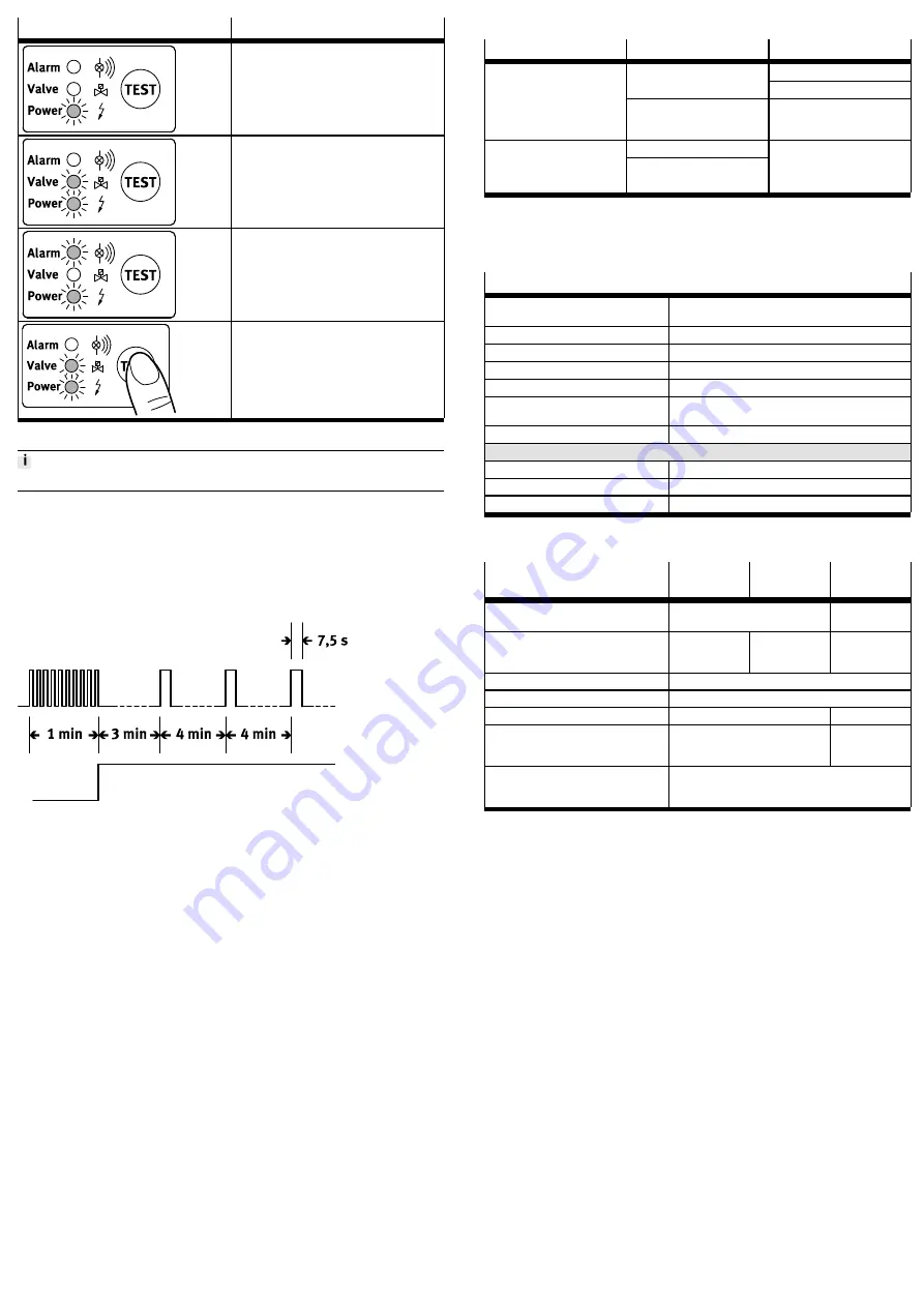
Operating status LEDs
Function
Ready for operation Voltage is present
Drain sequence Feed pipe is open
Malfunction/alarm
If there is a malfunction in the condensate drain,
the valve opens in cycles (approx. every 3 s) so
that the malfunction can be automatically
remedied.
Test of valve function (manual draining):
Actuate the pushbutton for approx. 2 s. Test of
alarm function
è
Alarm mode function: Actuate
the pushbutton for at least 1 minute.
Tab. 8 Operating status LEDs
Do not use the test pushbutton for continuous draining.
Alarm mode function
The PWEAAC/AP condensate drain also has an alarm mode function for malfunc
tions when draining the condensate. If the sensor is not free after 1 minute, a fault
message is triggered.
–
An alarm LED flashes.
–
An alarm relay switches. The signal can be transmitted potentialfree.
–
The valve opens every 4 minutes for 7.5 s.
Fig. 7
If the malfunction is remedied, the PWEAAC/AP condensate drain automatically
switches back to normal mode.
Potential-free fault message contact
The alarm signal can be forwarded via the potentialfree contact (e.g. to a control
station). The switching contact can, for example, be operated in failsafe mode.
–
The PWEAAC/AP condensate drain works faultfree when powered
è
The
alarm relay is activated.
–
If there is no operating voltage or if there is a fault message, the alarm relay
switches off
è
The working contact is open (alarm).
External test
Any existing condensate can be drained via remote control. The normal test push
button function also leads out of the PWEAAC/AD condensate drain here. If the
external contact is closed, the valve opens. The connection can be connected to a
switch, a relay contact or an open collector output.
6
Service
6.1
Cleaning and maintenance
•
Clean the PWEAAC/AP condensate drain, if required, with a soft cloth. Clean
ing agents include all nonabrasive media.
7
Malfunctions
Malfunction
Possible cause
Remedy
Check compressor.
Blocked drain pipe
Clean supply line.
Minimum pressure not reached
Error in the installation.
Perform installation in accord
ance with the instruction manu
al.
Overload
Condensate is too high
Extremely large quantities of
dirt particles
Observe maximum permissible
operating pressure
è
Tab. 9
8
Technical data
8.1
Technical data, pneumatic
Operating conditions
Permissible temperature
range
[°C]
+1 … +60
Operating medium
Compressed air
Operating pressure
[bar]
0.8 … 16
Mounting position
Standing upright ± 5°
Condensate feed
G
½
inside
Condensate drain (tubing)
G¼
@
8 … 9 mm angle nozzle
e.g. type PUNH12x2NT
Weight (empty)
[kg]
0.7
Materials
Housing
Polymer
Condensate reservoir
Al
Seals
NBR, FPM, PU
Tab. 10
8.2
Technical data, electrical
Electrical data PWEA-
AC/-AP
6A
7A
3D
Maximum power consump
tion
P < 2.0 VA
P < 2.0 W
Mains voltage
U
AC
=
115 V ±10 %
50 … 60Hz
U
AC
=
230 V ±10 %
50 … 60Hz
U
0
=
24 VDC
+10 … 25 %
1)
Recommended cable sheath
[
@
]
5.8…8.5 mm
Cable cross section
[mm
2
]
3 x 0.75, 5 x 0.25
Fuse protection
0.5 A
2)
100 mA
1)2)
Contact load / potentialfree
fault message
0 V … 250 V
0 mA … 1000 mA
5 V … 30 V
10 mA … 1000
mA
External test IN1 and 0V
Test active:
Test inactive:
IN1: 0 … 1 V contact closed
IN1: 5 … 36 V contact open
1) Minimum voltage source internal resistance Ri 12 Ohm
2) medium timelag
Tab. 11


