background image


© Festo Didactic


8030737 

13


3


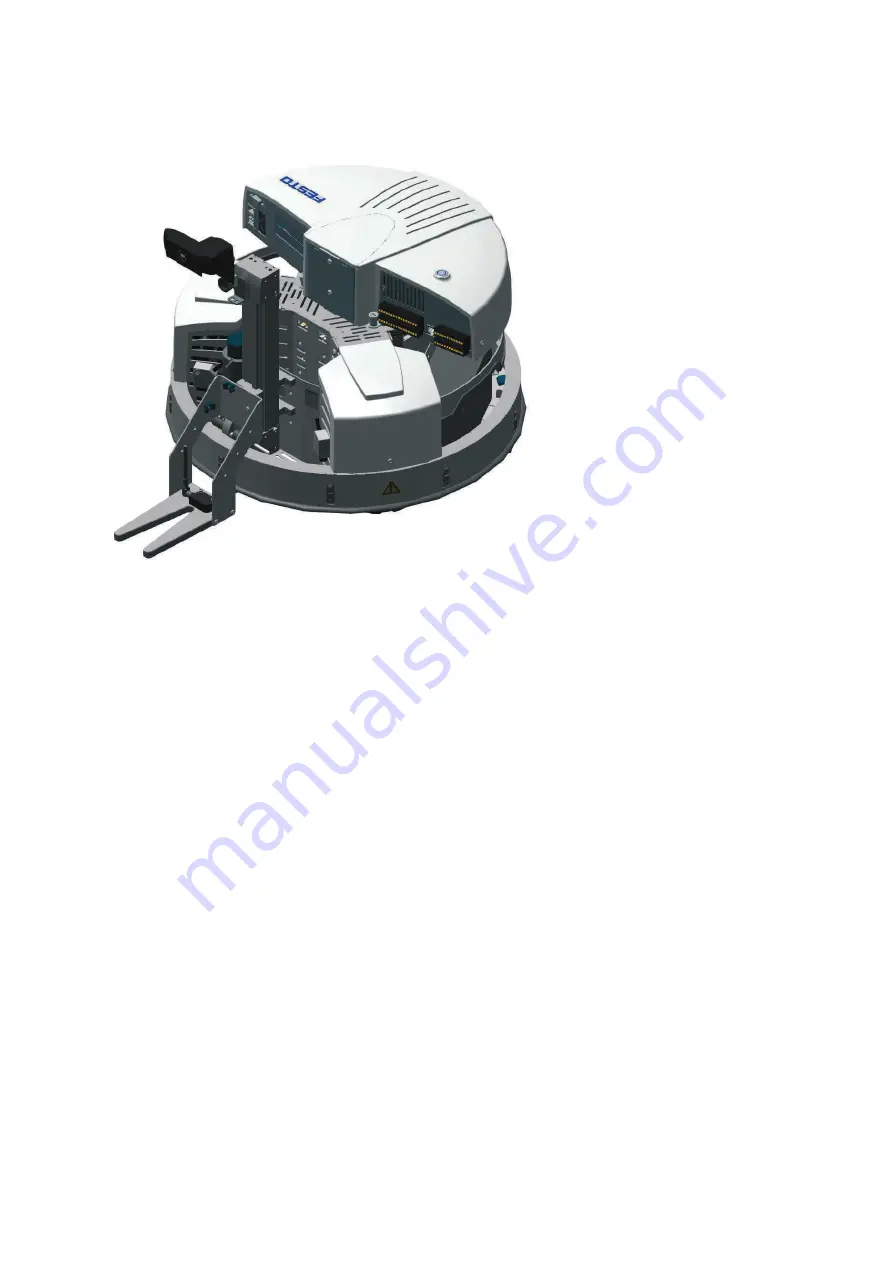
Forklift 


3.1


Function 

When equipped with the forklift module, the Robotino

®

 functions like a conventional conveyor vehicle. The 

forklift’s motor is connected to the fourth motor terminal at the Robotino

®

. 2 limit switches and a switch lug 

are attached in order to specify the maximum working range. The end positions are implemented by means 
of software only. 
 
With the help of Robotino

®

 View, you can move the axis within its working range and travel at different 

speeds. 
 
Proceed as follows in order to save the forklift positions to memory in Robotino

®

 View: 


Move the forks to the lowest possible point. 


Set the position value to 0 at the rotary encoder input function block. 


Advance the forklift to the desired position with the help of Robotino

®

 View. Use the power output 

function block to this end. 


Enter the rotary encoder’s current position value as a constant in order to be able to conduct a target-
actual comparison later on. 


Incremental travel is also possible if the actual position is reset to 0 after each travel operation. 

 
Be sure to observe the end positions of the linear axis in the Robotino

®

 View program. 


Summary of Contents for Robotino 8029453

Page 1: ...Festo Didactic 8030737 de en 09 2013 Abbildung hnlich similar illustration 8029453 Forklift Robotino Kurzbeschreibung Brief description...

Page 2: ...o didactic com 49 711 34754 88500 did de festo com The copying distribution and utilization of this document as well as the communication of its contents to others without expressed authorization is p...

Page 3: ..._____________9 3 5 Optionale Montage__________________________________________________________________9 Table of contents 1 Use for intended purpose ___________________________________________________...

Page 4: ...Lernsystem von Festo Didactic ist ausschlie lich f r die Aus und Weiterbildung im Bereich Automatisierung und Technik entwickelt und hergestellt Das Ausbildungsunternehmen und oder die Ausbildenden h...

Page 5: ...sch digen nderungen an der Verkabelung oder Umbauten in der Kommandobr cke auf eigene Gefahr unter Verlust der Garantie Verwenden Sie ausschlie lich Original Ersatzteile Nach dem Laden Ladeger t von R...

Page 6: ...en verfahren Um in Robotino View Positionen des Gabelstaplers zu speichern gehen Sie folgenderma en vor Fahren Sie die Aufnahme auf den niedrigsten Punkt Setzen Sie den Positionswert des Funktionsbaus...

Page 7: ...ensoren einbauen wollen sollten Sie diese zuerst montieren Montieren Sie das Modul an die vier markierten Gewinde der Adapterplatte Setzen Sie das Modul in die Ladebucht des Robotino Befestigen Sie da...

Page 8: ...Kommandobr cke an Die Leitungen vom Motor werden in der Ladebucht Inkrementalgeber links 2 und die Spannungsversorgung rechts 3 von Robotino angeschlossen Der optische Sensor wird wie folgt angeschlos...

Page 9: ...sich die Finger einklemmen 3 5 Optionale Montage Der Robotino bietet durch eine Erweiterung mit S ule und Segmenten die M glichkeit die Module auf verschiedene Ebenen und Positionen zu montieren Hierf...

Page 10: ...Gabelstapler 10 Festo Didactic 8030737...

Page 11: ...m Festo Didactic has been developed and manufactured exclusively for training and vocational education in the fields of automation and technology The respective training companies and or trainers must...

Page 12: ...ontact Modifications to the wiring or conversions in the command bridge are carried out at your own risk and nullify the warranty Only use genuine spare parts Disconnect charger from Robotino after ch...

Page 13: ...avel at different speeds Proceed as follows in order to save the forklift positions to memory in Robotino View Move the forks to the lowest possible point Set the position value to 0 at the rotary enc...

Page 14: ...install opto electric sensors this should be done first Mount the module on the four threads identified on the adapter plate Place the module into the Robotino loading bay Secure the module at both si...

Page 15: ...on the command bridge The cables from the motor are connected in Robotino s loading bay incremental encoder left 2 and power supply right 3 The opto electric sensor is connected as follows Brown 24 V...

Page 16: ...t caught in the mechanism 3 5 Optional assembly An expansion consisting of a mounting column and a mounting platform provides Robotino users with the opportunity of mounting the modules at different l...

Page 17: ......

Page 18: ......

Page 19: ......

Page 20: ...Festo Didactic SE Rechbergstra e 3 73770 Denkendorf Germany 49 711 3467 0 www festo didactic com 49 711 34754 88500 did de festo com...

Reviews: