2. Fitting
2−6
Festo P.BE−SBO−Q−EN en 0702a
2.1.3
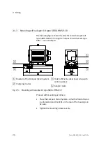
Mounting with adapter kit type SBOA−HMSV−39
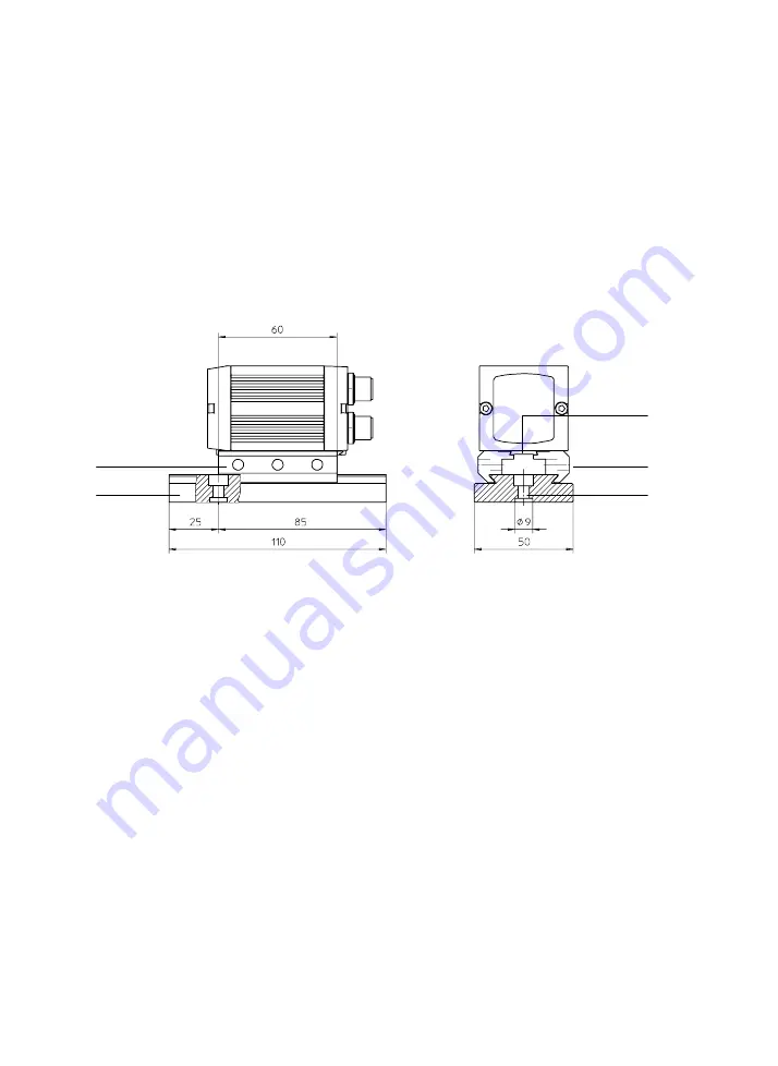
The following figure shows the attachment with adapter kit
type SBOA−HMSV−39 using the Compact Vision System type
SBOI−... as an example:
2
3
4
1
2
1
Dovetail of the Compact Vision System
2
Clamping devices
3
Hole for M5x16 socket head screw with
centring sleeve
4
Adapter plate
Fig.2/3:
Mounting with adapter kit type SBOA−HMSV−39
Proceed with mounting as follows:
·
Place the Compact Vision System so that the field of vision
is unhindered and the LEDs on the rear of the housing can
be seen.
·
Tighten the mounting screws evenly.
Summary of Contents for SBO Q Series
Page 2: ......
Page 8: ...Contents and general instructions VI Festo P BE SBO Q EN en 0702a ...
Page 19: ...System summary 1 1 Festo P BE SBO Q EN en 0702a Chapter 1 ...
Page 37: ...Fitting 2 1 Festo P BE SBO Q EN en 0702a Chapter 2 ...
Page 45: ...Installation 3 1 Festo P BE SBO Q EN en 0702a Chapter 3 ...
Page 60: ...3 Installation 3 16 Festo P BE SBO Q EN en 0702a ...
Page 61: ...Commissioning 4 1 Festo P BE SBO Q EN en 0702a Chapter 4 ...
Page 114: ...4 Commissioning 4 54 Festo P BE SBO Q EN en 0702a ...
Page 115: ...Diagnosis and error treatment 5 1 Festo P BE SBO Q EN en 0702a Chapter 5 ...
Page 122: ...5 Diagnosis and error treatment 5 8 Festo P BE SBO Q EN en 0702a ...
Page 123: ...Technical appendix A 1 Festo P BE SBO Q EN en 0702a Appendix A ...
Page 146: ...A Technical appendix A 24 Festo P BE SBO Q EN en 0702a ...
Page 147: ...Index B 1 Festo P BE SBO Q EN en 0702a Appendix B ...
Page 148: ...B Index B 2 Festo P BE SBO Q EN en 0702a Contents B Index B 1 B 1 Index B 3 ...
Page 156: ...B Index B 10 Festo P BE SBO Q EN en 0702a Z Zoom 1 14 ...

