3. Installation
3−6
Festo P.BE−SBO−Q−EN en 0702a
3.2
Electrical connections
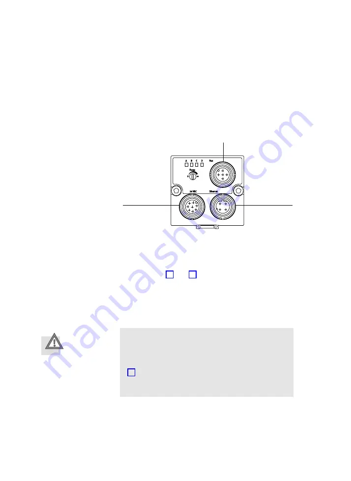
The following connection and display elements can be found
on the rear side of the Compact Vision System:
1
CAN interface
2
Ethernet interface
(plug M12x1)
3
Power supply and
digital I/Os
(plug M12x1)
1
2
3
Fig.3/1:
Electrical connections of the Compact Vision System type SBO...−...
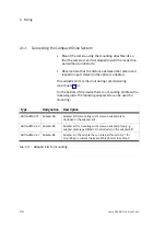
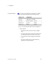
The following connection options are available
(see also chapter 4.9 and Tab.4/4).
3.2.1
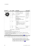
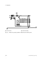
Connecting the operating voltage and I/Os
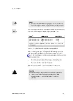
Caution
Damage to components
·
Make sure that the max. permissible operating voltage
range is not exceeded (see Technical Data, in appendix
A.4).
·
Protect the power supply of the Compact Vision System
externally with a fast acting 2 A micro fuse.
Summary of Contents for SBO Q Series
Page 2: ......
Page 8: ...Contents and general instructions VI Festo P BE SBO Q EN en 0702a ...
Page 19: ...System summary 1 1 Festo P BE SBO Q EN en 0702a Chapter 1 ...
Page 37: ...Fitting 2 1 Festo P BE SBO Q EN en 0702a Chapter 2 ...
Page 45: ...Installation 3 1 Festo P BE SBO Q EN en 0702a Chapter 3 ...
Page 60: ...3 Installation 3 16 Festo P BE SBO Q EN en 0702a ...
Page 61: ...Commissioning 4 1 Festo P BE SBO Q EN en 0702a Chapter 4 ...
Page 114: ...4 Commissioning 4 54 Festo P BE SBO Q EN en 0702a ...
Page 115: ...Diagnosis and error treatment 5 1 Festo P BE SBO Q EN en 0702a Chapter 5 ...
Page 122: ...5 Diagnosis and error treatment 5 8 Festo P BE SBO Q EN en 0702a ...
Page 123: ...Technical appendix A 1 Festo P BE SBO Q EN en 0702a Appendix A ...
Page 146: ...A Technical appendix A 24 Festo P BE SBO Q EN en 0702a ...
Page 147: ...Index B 1 Festo P BE SBO Q EN en 0702a Appendix B ...
Page 148: ...B Index B 2 Festo P BE SBO Q EN en 0702a Contents B Index B 1 B 1 Index B 3 ...
Page 156: ...B Index B 10 Festo P BE SBO Q EN en 0702a Z Zoom 1 14 ...

