3. Installation
3−9
Festo P.BE−SBO−Q−EN en 0702a
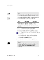
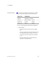
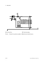
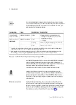
Connection example
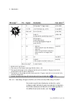
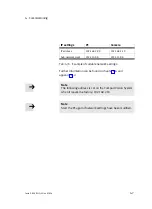
Fig.3/2 shows an example of the connection for a configur
ation of the system parameters with the default values:
Internal I/Os
Configuration
Polarity I0
Trigger signal = rising edge
Polarity O0
Ready for operation = logical 1
Function at O1
Good part
= logical 1
Function at O2
Bad part
= logical 1
Tab.3/4: System parameters with standard configuration
·
Please note that:
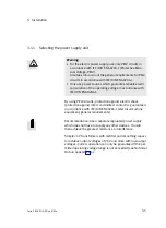
the tolerance of 24 V DC ±10 % must be complied
with.
the power supply of the Compact Vision System must
be protected externally. Fast−acting 2 A micro fuse.
the residual current of all outputs must not exceed
1.5A.
the cable screening must be connected with low
impedance to the earth potential.
Summary of Contents for SBO Q Series
Page 2: ......
Page 8: ...Contents and general instructions VI Festo P BE SBO Q EN en 0702a ...
Page 19: ...System summary 1 1 Festo P BE SBO Q EN en 0702a Chapter 1 ...
Page 37: ...Fitting 2 1 Festo P BE SBO Q EN en 0702a Chapter 2 ...
Page 45: ...Installation 3 1 Festo P BE SBO Q EN en 0702a Chapter 3 ...
Page 60: ...3 Installation 3 16 Festo P BE SBO Q EN en 0702a ...
Page 61: ...Commissioning 4 1 Festo P BE SBO Q EN en 0702a Chapter 4 ...
Page 114: ...4 Commissioning 4 54 Festo P BE SBO Q EN en 0702a ...
Page 115: ...Diagnosis and error treatment 5 1 Festo P BE SBO Q EN en 0702a Chapter 5 ...
Page 122: ...5 Diagnosis and error treatment 5 8 Festo P BE SBO Q EN en 0702a ...
Page 123: ...Technical appendix A 1 Festo P BE SBO Q EN en 0702a Appendix A ...
Page 146: ...A Technical appendix A 24 Festo P BE SBO Q EN en 0702a ...
Page 147: ...Index B 1 Festo P BE SBO Q EN en 0702a Appendix B ...
Page 148: ...B Index B 2 Festo P BE SBO Q EN en 0702a Contents B Index B 1 B 1 Index B 3 ...
Page 156: ...B Index B 10 Festo P BE SBO Q EN en 0702a Z Zoom 1 14 ...

