4. Commissioning
4−39
Festo P.BE−SBO−Q−EN en 0702a
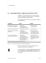
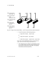
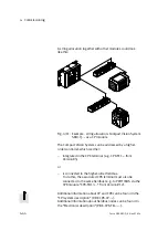
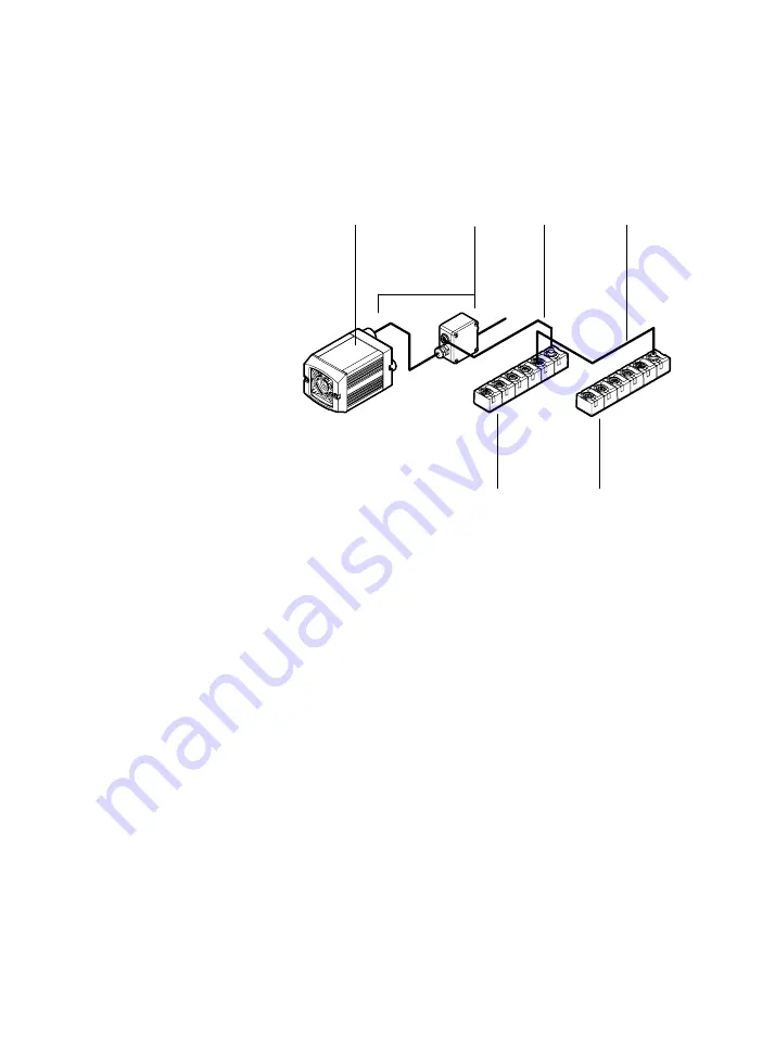
1
Compact Vision
System SBO...−Q
2
Cable for power
input
SBOA−K20CP−SUP
3
Connecting cable
KVI−CP−3−...
4
Input module
CP−E08−M12−CL
(max. 1)
5
Output module
CP−A04−M12−CL
(max. 1)
24 V
1
2
3
4
5
3
Fig.4/10: Compact Vision System SBOI−Q−... with I/O expansion (here maximum expansion)
·
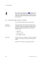
Connect the modules in the following sequence:
Compact Vision System output module
or
Compact Vision System input module
or
Compact Vision System output module input module
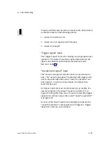
The 0 V line of cable SBOA−K20CP−SUP
2
is connected electri
cally to the 0 V line of the Compact Vision System
1
.
·
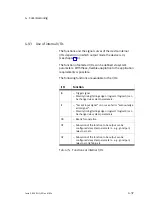
Use suitable measures in order to avoid equalizing currents,
e. g. a common power unit for the compact camera system
and the power supply for the I/O modules, or by separate
low−impedance potential equalization.
Summary of Contents for SBO Q Series
Page 2: ......
Page 8: ...Contents and general instructions VI Festo P BE SBO Q EN en 0702a ...
Page 19: ...System summary 1 1 Festo P BE SBO Q EN en 0702a Chapter 1 ...
Page 37: ...Fitting 2 1 Festo P BE SBO Q EN en 0702a Chapter 2 ...
Page 45: ...Installation 3 1 Festo P BE SBO Q EN en 0702a Chapter 3 ...
Page 60: ...3 Installation 3 16 Festo P BE SBO Q EN en 0702a ...
Page 61: ...Commissioning 4 1 Festo P BE SBO Q EN en 0702a Chapter 4 ...
Page 114: ...4 Commissioning 4 54 Festo P BE SBO Q EN en 0702a ...
Page 115: ...Diagnosis and error treatment 5 1 Festo P BE SBO Q EN en 0702a Chapter 5 ...
Page 122: ...5 Diagnosis and error treatment 5 8 Festo P BE SBO Q EN en 0702a ...
Page 123: ...Technical appendix A 1 Festo P BE SBO Q EN en 0702a Appendix A ...
Page 146: ...A Technical appendix A 24 Festo P BE SBO Q EN en 0702a ...
Page 147: ...Index B 1 Festo P BE SBO Q EN en 0702a Appendix B ...
Page 148: ...B Index B 2 Festo P BE SBO Q EN en 0702a Contents B Index B 1 B 1 Index B 3 ...
Page 156: ...B Index B 10 Festo P BE SBO Q EN en 0702a Z Zoom 1 14 ...

