SDE1−...
Festo SDE1−... 0511e English
40
5
Installation
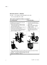
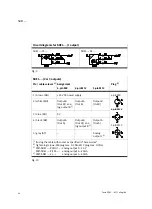
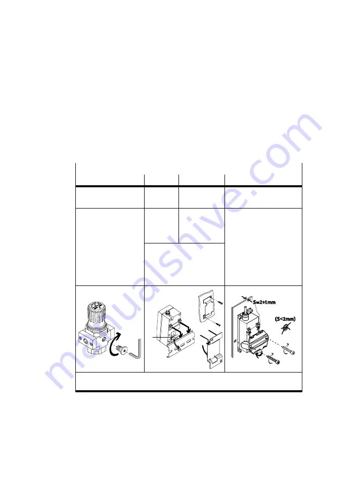
Mechanical(...−R14/R18/H../W../FQ4)
S
Fasten the SDE1−... in the intended position.
SDE1−G2−...
R14/R18
H..
W..
FQ4
MS− or D−series service
unit
Hat rail
Wall/surface
mounting
Front panel mounting
S
Fasten the adapter
with no more than the
following torque
1)
R14−...: 12 Nm
R18
: 7 Nm
S
Install the
adapter plate
(e.g. 2 x M3)
Maximum tightening
torque: 0.5 Nm (clamping
plate against front panel)
1. Guide SDE1−... into the
cut out (85 5 x 36 mm) on
R18−...: 7 Nm
Additional sealing of the
PTFE−coated connecting
thread is not necessary.
S
Attach the SDE1−... onto
the hat rail or adapter
plate and press until the
fastening slide (a) clips in.
cut−out (85.5 x 36 mm) on
the front panel. Attach
the clamping plate and
press until the fastening
slide clips in.
2. Screw in the screws
2)
a
1)
Using an Allen key width across flats 5 mm
2)
If the front panel thickness is less than 2 mm,
do not
use washers.
Fig.5
Summary of Contents for SDE1 Series
Page 30: ...SDE1 Festo SDE1 0511e Deutsch 30 Bild 23 EDIT Modus ...
Page 32: ...SDE1 Festo SDE1 0511e Deutsch 32 Bild 24 TEACH Modus ...
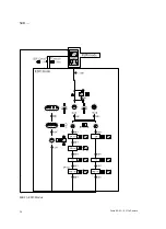
Page 60: ...SDE1 Festo SDE1 0511e English 60 Fig 23 EDIT mode ...
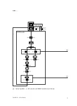
Page 62: ...SDE1 Festo SDE1 0511e English 62 Fig 24 TEACH mode ...
Page 63: ...SDE1 Festo SDE1 0511e 63 de Lochbilder Adapterplatte en Hole pattern on adapter plate ...


