Festo SOEL-...1606d English
25
SOEL-
Electrical installation
Warning: Pin 1 and pin 5 must not be connected to operational voltage as this will destroy the SOEL-
RTD-Q50-PP-S-7L sensor.
Insert the socket of the connection cable into the SOEL-RTD-Q50-PP-S-7L connector and screw tight.
The following table is valid for other electrical connections of the cable conductors:
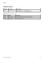
Connection
Colour
Use
Comments
1 (WH)
White
2 (BN)
Brown
+ U
B
3 (GN)
Green
As signal output Q
1
or input with optional input functions (see
“Settings” page 32)
Q
1
4 (YE)
Yellow
As signal output Q
2
or switching function “good target” (detectable
object in measuring range)
Q
2
or good target
5 (GY)
Grey
6 (PK)
Pink
Q
A
+ analogue measurement
7 (BU)
Blue
- U
B
8 (RD)
Red
Q
A
- analogue mass
Once power supply has been connected, the SOEL-RTD-Q50-PP-S-7L is ready for operation after a short stand-by delay
(< 300 ms).
Illustr. 8
Connection diagram
15400127
2
+U
B
QA 4...20 mA
Q2
Q1
-U
B
BN
1
WH
5
GY
6
PK
8
RD
4
YE
3
GN
7
BU
PNP
PNP
N.C.
N.C.
Summary of Contents for SOEL-RTD-Q50-PP-S-7L
Page 2: ......
Page 4: ...4 Inhalt Content Contenu Deutsch 5 English 21 Français 37 ...
Page 20: ...Festo SOEL 1606d Deutsch 20 SOEL ...
Page 36: ...Festo SOEL 1606d English 36 SOEL ...
Page 52: ...Festo SOEL 1606d Française SOEL 52 ...
Page 53: ......

