3. Installation
3-8
Festo P.BE-SPC11-SYS-ASI-EN en 0203NH
Proportional directional control valve (
5
)
Arrange the tubing between the valve (MPYE-5-...) and the
drive symmetrically.
Recommendation for linear drives and drives with piston rod:
tubing length = cylinder length.
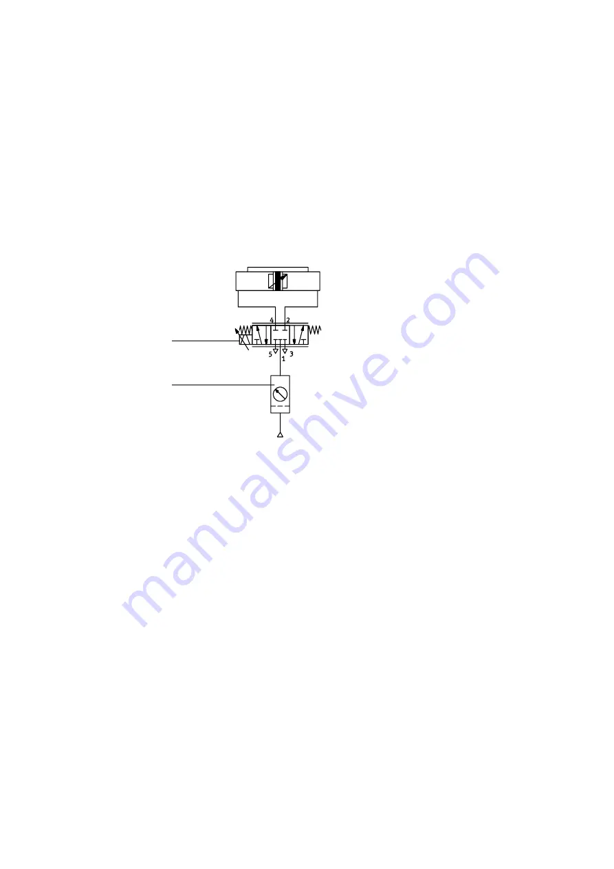
The diagram below shows as an example the tubing of a cylin-
der with an MPYE-5-... when an SPC11 is used without an
emergency stop circuit.
1
2
1
Proportional directional control valve type MPYE-5-...-...
2
Service unit with 5 µm filter without lubricator
Fig. 3/2: Pneumatic circuit diagram
Fit the valve in accordance with the operating instructions
supplied with the valve.
Summary of Contents for Soft Stop SPC11 Series
Page 2: ......
Page 14: ...Contents and general instructions XII Festo P BE SPC11 SYS ASI EN en 0203NH ...
Page 15: ...Summary of components 1 1 Festo P BE SPC11 SYS ASI EN en 0203NH Chapter 1 ...
Page 25: ...Fitting 2 1 Festo P BE SPC11 SYS ASI EN en 0203NH Chapter 2 ...
Page 28: ...2 Fitting 2 4 Festo P BE SPC11 SYS ASI EN en 0203NH ...
Page 29: ...Installation 3 1 Festo P BE SPC11 SYS ASI EN en 0203NH Chapter 3 ...
Page 61: ...Commissioning 4 1 Festo P BE SPC11 SYS ASI EN en 0203NH Chapter 4 ...
Page 100: ...4 Commissioning 4 40 Festo P BE SPC11 SYS ASI EN en 0203NH ...
Page 101: ...Diagnosis and error treatment 5 1 Festo P BE SPC11 SYS ASI EN en 0203NH Chapter 5 ...
Page 114: ...5 Diagnosis and error treatment 5 14 Festo P BE SPC11 SYS ASI EN en 0203NH ...
Page 127: ...Technical appendix B 1 Festo P BE SPC11 SYS ASI EN en 0203NH Appendix B ...


