Pressure sensor SPAN
Festo AG & Co. KG
Postfach
73726 Esslingen
Germany
+49 711 347-0
www.festo.com
Operating instructions
8049275
1607
[8049280]
Original: de
Pressure sensor SPAN
English
. . . . . . . . . . . . . . . . . . . . . . . . . . . . . . . . . . . . . . . . . .
1
Product description
The operating instructions describe the entire function range. The function range is
limited, depending on the product variant.
Note
You can find detailed specifications for the product, the device description file
(IODD) with a description of the IO-Link parameters and the declaration of con
formity at:
è
www.festo.com/sp.
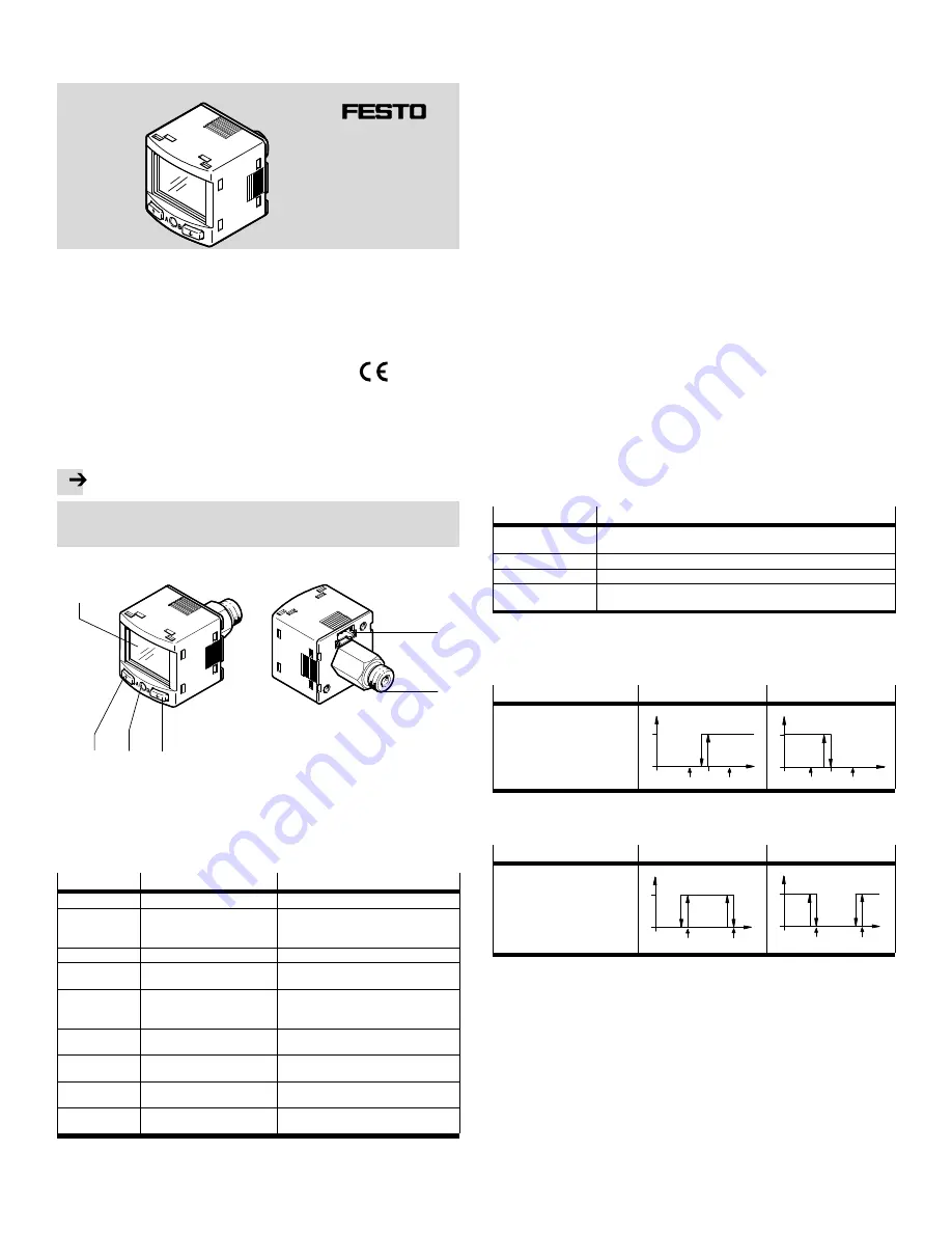
1.1 Overview
1
2
3
4
5
6
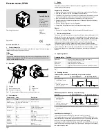
1
Display
2
Electrical connection
3
Pneumatic connection
4
B-key
5
Edit button
6
A-key
Fig. 1
Representation of other variants can deviate from this
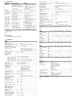
1.2 Characteristics
Characteristic
Value
Description
Type
SPAN
Pressure sensor
Pressure
measuring range
-B2, -B11, -P025, -P05, -P1, -P2,
-P6, -P10, -P12, -P16, -V025,
-V05, -V1
è
Technical data
Supply port
R
Relative pressure
Pneumatic port
-G18, -R18, N18, -M5,
-Q4,
Thread G
x
, R
x
, NPT
x
, M5
Push-in connector
4 mm
Thread type
M
F
None
Male thread
Female thread
Electrical
output 1
-PNLK
-PN
Switching output PNP / NPN / IO-Link
PNP / NPN
Electrical
output 2
-PNVBA
-PN
PNP / NPN / 0…10 V / 1…5 V / 4…20 mA
PNP / NPN
Electrical
connection
-L1
Plug connector, design L1
Certificate
+T
Without
With inspection report
Fig. 2
2
Safety
Intended use
The pressure sensor SPAN is intended for monitoring pressure of compressed air
and inert gases in the piping.
General safety information
Only use the product in its original status, without any unauthorised modifications.
Only use the product if it is in an excellent technical status.
The product is intended for use in industrial environments. Measures may need
to be implemented in residential areas for radio interference suppression.
Take into consideration the ambient conditions at the location of use.
Operate the product only with compressed air of the specified air quality class
(
è
Technical data).
Observe the specifications on the rating plate.
Comply with all applicable national and international regulations.
Disposal
Observe the local specifications for environmentally friendly disposal.
3
Function and application
The sensor converts pneumatic pressure values (relative pressure) into electrical
signals, which can be used for control or regulating functions.
Measurements are
carried out using a piezoresistive sensor element with a following electronic evalu
ation unit. Interfacing to the higher-level system is provided by 1 or 2 switching
outputs, an optional analogue output and an optional IO-Link interface.
The switching outputs can be configured for monitoring of a threshold value,
a pressure range or a differential pressure. The outputs can be set as PNP or NPN
and normally open (NO) or normally closed (NC). Via the IO-Link interface, process
values can be read out and parameters changed and transmitted to additional
devices.
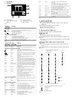
3.1 Operating statuses
Operating status
Function
RUN mode
– Basic status after the operating voltage is switched on
– Display of the current measured value
SHOW mode
– Display of the current settings
EDIT mode
– Setting or modification of parameters
TEACH mode
– Acceptance of the current measured value to determine switching
points
Fig. 3
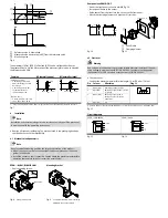
3.2 Switching functions
Threshold value comparator for monitoring of a pressure threshold
Function
NO (normally open)
NC (normally closed)
Switching function:
– 1 switching point (SP)
TEACH mode:
– 2 teach-in points (TP1, TP2)
– SP = ½ (TP1+TP2)
TP1 TP2
HY
1
0
Out
p
SP
TP1 TP2
SP
HY
1
0
Out
p
Fig. 4
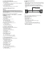
Window comparator for monitoring of a pressure range
Function
NO (normally open)
NC (normally closed)
Switching function:
– 2 Switching points
(SP.Lo, SP.Hi)
TEACH mode
1)
:
– 2 teach-in points (TP1, TP2)
– TP1 = SP.Lo, TP2 = SP.Hi
HY HY
TP1=SP.Lo TP2=SP.Hi
1
0
Out
p
HY HY
TP1=SP.Lo TP2=SP.Hi
1
0
Out
p
1)
SP.Lo = smaller pressure/vacuum value, SP.Hi = larger pressure/vacuum value, dependent on the
Teach sequence
Fig. 5
Auto difference monitoring d_|¯|_
This funciton permits monitoring of a pressure value for constancy.
If the applied pressure is constant in the range between [SP.Lo] and [SP.Hi], the refer
ence pressure PRef is automatically determined. The result is a switching operation at
the output. The signal change signals the start of pressure monitoring.
If the pressure remains in the monitoring range [d.SP] around PRef, the pressure is
stable. When the monitoring range is left (e.g. caused by a leakage in the system),
the output switches back.


