background image

Festo  VIFB6−..−    0208a    English

17

4

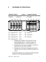
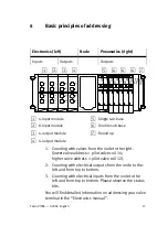
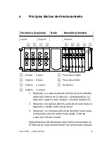
Basic  principles  of  addressing

Electronics  (left)

Node

Pneumatics  (right)

Inputs

Outputs

Outputs

1

2

3

4

5

6

7

6

6

1

4−input  module

2

8−input  module

3

4−output  module

4

4−output  module

5

Single  sub−base

6

Double  sub−base

7

Round  up

1. Counting  with  valves  from  the  node  to  the  right.

(lower  valve  address  =  pilot  valve  coil  14;
higher  valve  address  =  pilot  valve  coil  12).

2. Counting  with  electrical  outputs  from  the  node  to  the

left  and  from  top  to  bottom.

3. Counting  with  electrical  inputs  from  the  node  to  the

left  and  from  top  to  bottom.  Please  observe  the  status
bits.

You  will  find  detailed  information  on  addressing  your  valve
terminal  in  the  Electronics  manual".

Summary of Contents for VIFB6-03 Series

Page 1: ...eibung Brief description Feldbusknoten 6 f r Ventilinsel Typ 03 05 VIFB6 Fieldbus node 6 for valve termi nal type 03 05 VIFB6 Deutsch English Espa ol Fran ais Italiano Svenska 669 788 0208a Ventilinse...

Page 2: ...208a 2 Deutsch 3 English 11 Espa ol 19 Fran ais 27 Italiano 35 Svenska 43 Edition 0208a Original de Festo AG Co KG D 73726 Esslingen Germany 2003 Internet http www festo com E Mail service_internation...

Page 3: ...S Schalten Sie die Spannung aus bevor Sie Steckver binder zusammen stecken oder trennen Funktions sch digung S Verwenden Sie nur Netzteile die eine sichere elektri sche Trennung der Betriebsspannung...

Page 4: ...der Kontaktfl chen an Steckverbindungen und Missachtung der Handha bungsvorschriften f r elektrostatisch gef hrdete Bau elemente k nnen die Komponenten zerst ren Bei einer regul ren Inbetriebnahme mus...

Page 5: ...a Deutsch 5 1 2 1 INTERBUS Schnittstelle 2 DIL Schalter f r Ventiltest bzw Fehlermeldungen 2 1 DIL Schaltereinstellung DIL Schalter k Ventiltest Fehlermeldungen Werk sinstel lung AUS EIN teilweise sen...

Page 6: ...utsch 6 3 Anschlussbelegung Spannungsversorgung 1 2 3 4 1 24 V Versorgung Elektronik undEing nge 2 24 V Versorgung Ventile undAusg nge 3 0 V 4 Erdungsanschluss 3 1 Bedeutung der LED Anzeigen Siehe Bes...

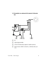
Page 7: ...3 2 Schaltungsbeispiel Betriebsspannungsanschluss 10 A 24 V 3 15 A 0 V 1 3 2 4 3 1 2 4 1 2 3 4 2 1 PE 2 Potenzialausgleich 3 Betriebsspannung getrennt abschaltbar externe Siche rungen 4 Erdungsanschlu...

Page 8: ...gsleiter FunktionserdeInst fern bus Inst fernbusversorgung Inst fernbusversorgung Schirmung OUT Pin Nr Be zeich nung Bedeutung 1 2 3 4 5 6 7 8 9 H lse DO DO DI DI Masse FE 24 V 0 V RBST Schirm Data ou...

Page 9: ...6 Impulsblock 7 Aufrunden 1 Z hlweise bei Ventilen vom Knoten nach rechts niederwertige Adresse Vorsteuermagnet 14 h herwertige Adresse Vorsteuermagnet 12 2 Z hlweise bei elektrischen Ausg ngen vom Kn...

Page 10: ...polungssicher Toleranz zul Gesamtstrom DC 24 V 25 DC 18 V 30 V max 2 2 A Pin 2 Betriebsspannungsanschluss Ausg nge Ventile Nennwert verpolungssicher Toleranz zul Gesamtstrom DC 24 V 10 DC 21 6 V 26 4...

Page 11: ...he power supply before connecting or disconnecting plugs otherwise this could lead to functional damage S Use only power units which guarantee reliable isola tion of the operating voltages as per IEC...

Page 12: ...liable to damage by electrostatic charges The components can also be destroyed if the contact surfaces of plug connectors are touched or if the re gulations for handling electrostatically vulnerable...

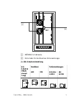
Page 13: ...o VIFB6 0208a English 13 1 2 1 INTERBUS interface 2 DIL switch for valve test and error messages 2 1 Setting the DIL switch DIL switch Valve test Error messages s factory setting OFF ON Send part Send...

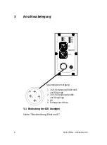
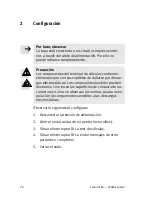
Page 14: ...ish 14 3 Pin assignment Operating voltage 1 2 3 4 1 24 V supply for electronic components and inputs 2 24 V supply for valves and outputs 3 0 V 4 Earth connection 3 1 Meaning of the LED displays Refer...

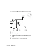
Page 15: ...it example of operating voltage connection 10 A 24 V 3 15 A 0 V 1 3 2 4 3 1 2 4 1 2 3 4 2 1 PE 2 Potenzial equalization 3 Operating voltage can be switched off separately exter nal fuses 4 Earth cable...

Page 16: ...rse Reference conductor Functional earth for remote bus Remote bus supply Remote bus supply Screening OUT Pin no Desig nation Meaning 1 2 3 4 5 6 7 8 9 Sleeve DO DO DI DI Earth FE 24 V 0 V RBST Screen...

Page 17: ...b base 7 Round up 1 Counting with valves from the node to the right lower valve address pilot valve coil 14 higher valve address pilot valve coil 12 2 Counting with electrical outputs from the node to...

Page 18: ...ect polarity Tolerance Permitted current consumption DC 24 V 25 DC 18 V 30 V max 2 2 A Pin 2 Operating voltage connection for outputs valves Rated value protected against incorrect polarity Tolerance...

Page 19: ...la fuente de alimentaci n antes de in sertar o retirar conectores de lo contrario pueden producirse da os S Utilizar solamente fuentes de alimentaci n que ga ranticen un aislamiento fiable de las ten...

Page 20: ...descar gas electrost ticas Los componentes tambi n pueden destruirse si se tocan las superficies de contacto de los conectores o si no se observan las normas para la mani pulaci n de componentes sens...

Page 21: ...21 1 2 1 Interface INTERBUS 2 Interruptor DIL para test de v lvulas y mensajes de error 2 1 Ajuste del interruptor DIL Interrup tor DIL Test de v lvulas Mensajes de error ajustes de ori gen OFF ON En...

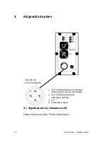
Page 22: ...es Tensi n de funcionamiento 1 2 3 4 1 24 V alimentaci n para compo nentes electr nicos y entradas 2 24 V alimentaci n para v lvulas y salidas 3 0 V 4 Conexi n a tierra 3 1 Significado de los indicado...

Page 23: ...la conexi n de la tensi n de alimentaci n 10 A 24 V 3 15 A 0 V 1 3 2 4 3 1 2 4 1 2 3 4 2 1 PE 2 Ecualizaci n de potencial 3 La tensi n de alimentaci n puede desconectarse por separado fusibles extern...

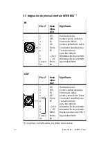
Page 24: ...ia Tierra funcional para bus remoto Alimentaci n bus remoto Alimentaci n bus remoto Apantallamiento OUT Pin n Deno mina ci n Significado 1 2 3 4 5 6 7 8 9 Casqui llo DO DO DI DI Tierra FE 24 V 0 V RBS...

Page 25: ...on v lvulas desde el nodo hacia la derecha direcci n inferior de la v lvula pilotaje bobina 14 direcci n superior de la v lvula pilotaje bobina 12 2 Recuento con salidas el ctricas desde el nodo hacia...

Page 26: ...ad incorrecta Tolerancia Consumo de corriente permi tido DC 24 V 25 DC 18 V 30 V m x 2 2 A Pin 2 Conexi n de la tensi n de alimentaci n para outputs v l vulas Valor nominal protegido con tra polaridad...

Page 27: ...us amples informations Avertissement S Mettre hors tension avant de raccorder ou de d bran cher des connecteurs risque de d gradations S Utiliser syst matiquement une alimentation isol e conforme la n...

Page 28: ...ag s en touchant la main les surfaces de contact des connecteurs ou en ne respec tant pas les prescriptions relatives la manipulation des composants sensibles aux charges lectrostati ques Lors d une m...

Page 29: ...TERBUS 2 Interrupteur DIL pour le r glage du test des distributeurs ou des messages d erreurs 2 1 R glage de l interrupteur DIL Interrup teur DIL l Test des distribu teurs Messages d erreur r glage en...

Page 30: ...n des broches Tension d alimentation 1 2 3 4 1 Alimentation 24 V de l lectronique et des entr es 2 Alimentation 24 V des distributeurs et des sorties 3 0 V 4 Borne de terre 3 1 Signification des t moi...

Page 31: ...emple de raccordement de la tension d alimenta tion 10 A 24 V 3 15 A 0 V 1 3 2 4 3 1 2 4 1 2 3 4 2 1 PE 2 Ligne quipotentielle 3 Tension d alimentation s par e Fusibles externes 4 Borne de terre reli...

Page 32: ...e terre fonction nelle bus d installation Alim bus d installation Alim bus d installation Blindage OUT Broche D sign Signification 1 2 3 4 5 6 7 8 9 Douille DO DO DI DI Masse FE 24 V 0 V RBST Blin dag...

Page 33: ...stributeur bistable 7 Arrondi 1 Pour les distributeurs comptage partir du noeud et vers la droite adresse de poids faible bobine de pilotage 14 adresse de poids fort bobine de pilo tage 12 2 Pour les...

Page 34: ...ontre l inversion de polarit Tol rance Courant total max DC 24 V 25 DC 18 V 30 V max 2 2 A Broche 2 du connecteur d ali mentation distributeurs sorties Tension nom prot g contre l inversion de polarit...

Page 35: ...vare la tensione prima di inserire o disinserire i connettori pericolo di danni funzionali S Utilizzare esclusivamente alimentatori in grado di garantire un sezionamento elettrico sicuro della tension...

Page 36: ...nnesto e non rispettando le norme per la manipolazione degli elementi sensibili alle cariche elettrostatiche si pu provocare la distruzione dei com ponenti Se la messa in servizio viene eseguita in mo...

Page 37: ...accia INTERBUS 2 Interruttori DIL per test valvole e segnalazioni di errore 2 1 Impostazione degli interruttori DIL Interrut tori DIL Test delle valvole Segnalazioni di er rore OFF ON invio selettivo...

Page 38: ...pazione dei pin Tensione di esercizio 1 2 3 4 1 Alimentazione a 24 V elettronica e ingressi 2 Alimentazione a 24 V valvole e uscite 3 0 V 4 Connessione di terra 3 1 Significato dei LED Fare riferiment...

Page 39: ...llegamento connettore tensione di esercizio 10 A 24 V 3 15 A 0 V 1 3 2 4 3 1 2 4 1 2 3 4 2 1 PE 2 Compensazione di potenziale 3 Disinserzione separata della tensione di esercizio Fusi bili esterni 4 P...

Page 40: ...emoto di inst Alimentazione bus re moto di inst Alimentazione bus re moto di inst Schermatura OUT N pin Nome Significato 1 2 3 4 5 6 7 8 9 Ca vetto DO DO DI DI Massa FE 24 V 0 V RBST Schermo Output da...

Page 41: ...tondamento 1 Conteggio per le valvole procedendo dal nodo verso destra indirizzo pi basso solenoide pilota 14 indirizzo pi alto solenoide pilota 12 2 Conteggio per le uscite elettriche procedendo dal...

Page 42: ...max assorbimento elettrico totale DC 24 VCC 25 18 VCC 30 VCC max 2 2 A Pin 2 connessione tensione di esercizio per uscite valvole valore nominale a prova di inversione di polarit tolleranza max assor...

Page 43: ...ning S Koppla fr n sp nningen innan stickkontakter ansluts eller dras ut risk f r funktionsskada S Anv nd endast n tdelar som garanterar en s ker elektrisk isolering av driftsp nningen enligt IEC 742...

Page 44: ...elektroniskt k nsliga komponenter Ber ring av kontaktytor p kon takterna och hantering som strider mot anv ndningsf reskrifterna f r elektrostatiskt k nsliga komponenter kan medf ra att komponenterna...

Page 45: ...08a Svenska 45 1 2 1 INTERBUS gr nssnitt 2 DIL kontakter f r ventiltest resp felmeddelanden 2 1 DIL kontaktens position DIL kon takt Ventiltest Felmeddelanden a fabriks inst ll ning FR N TILL s nd del...

Page 46: ...a Svenska 46 3 Stiftbel ggning Driftsp nning 1 2 3 4 1 24 V f rs rjning elektronik och ing ngar 2 24 V f rs rjning ventiler och utg ngar 3 0 V 4 Jordanslutning 3 1 LED indikeringarnas betydelser Se Ma...

Page 47: ...nska 47 3 2 Kopplingsexempel driftsp nningsanslutning 10 A 24 V 3 15 A 0 V 1 3 2 4 3 1 2 4 1 2 3 4 2 1 PE 2 Potenzialutj mning 3 Drift sp nning separat fr nkopp lingsbar Externa s kringar 4 Jordanslut...

Page 48: ...re Funktionsjordning f r Inst fj rrbuss Inst fj rrbussf rs rjning Inst fj rrbussf rs rjning Sk rmning OUT Stift nr Be teck ning Betydelse 1 2 3 4 5 6 7 8 9 Hylsa DO DO DI DI Massa FE 24 V 0 V RBST Sk...

Page 49: ...bilt anslutnings block 6 Bistabilt anslutningsblock 7 Avrunda upp t 1 R kna ventilerna fr n noden t h ger adress med l ngre signifikans magnetspole 14 adress med h gre signifikans magnetspole 12 2 R k...

Page 50: ...polomkast ningss kert Tolerans Till totalstr m DC 24 V 25 DC 18 V 30 V max 2 2 A Stift 2 Driftsp nningsanslut ning utg ngar ventiler Normv rde polomkast ningss kert Tolerans Till totalstr m DC 24 V 1...

Reviews: