VPPM−...−DE/E N
Festo VPPM−... 0810b English
35
S
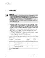
The individual pins are assigned at the electrical connection as follows:
Pin
Cable
colours
1)
Connection designation
M12 plug
2)
colours
1)
Voltage variant
type
VPPM−...−V1...
Current variant
type
VPPM−...−A4...
1
White (WH)
Digital input D1
8
2
Brown (BN)
+24 V DC power supply
1
2
8
3
Green (GN)
Analogue input W− (− setpoint value)
1
2
4
Yellow (YE)
Analogue input
W+ (+ setpoint
value) 0 ... 10 V
Analogue input
W+ (+ setpoint
value) 4 ... 20 mA
3
7
5
Grey (GY)
Digital input D2
3
6
Pink (PK)
Analogue output X (actual value)
6
4
7
Blue (BU)
0 V DC or GND
5
6
4
8
Red (RD)
Digital output D3
3)
5
PE braided screen on thread
1)
Using the connection socket with cable as specified in the chapter Accessories"
2)
The max. tightening torque is 0.5 Nm.
3) The hysteresis of the digital comparator output D3 is 0.5% Fs.
Fig.13


