background image

Contents  and  general  instructions

I

Festo  P.BE−MPA−EN    en  0302NH

Author

M.  Simons

.  .  .  .  .  .  .  .  .  .  .  .  .  .  .  .  .  .  .  .  .  .  .  .  .  .  .  .  .  .  .  .  . 

Editor

M.  Holder

.  .  .  .  .  .  .  .  .  .  .  .  .  .  .  .  .  .  .  .  .  .  .  .  .  .  .  .  .  .  .  .  .  .  . 

Original

de

.  .  .  .  .  .  .  .  .  .  .  .  .  .  .  .  .  .  .  .  .  .  .  .  .  .  .  .  .  .  .  .  .  .  .  .  .  .  . 

Layout

Festo  AG  &  Co.  KG,  Dept.  KG−GD

.  .  .  .  .  .  .  .  .  .  .  .  .  .  .  . 

Type  setting

KI−DT

.  .  .  .  .  .  .  .  .  .  .  .  .  .  .  .  .  .  .  .  .  .  .  .  .  .  .  .  .  .  .  .  .  . 

Edition

en  0302NH

.  .  .  .  .  .  .  .  .  .  .  .  .  .  .  .  .  .  .  .  .  .  .  .  .  .  .  .  .  .  .  .  . 

Designation     

P.BE−MPA−EN

.  .  .  .  .  .  .  .  .  .  .  .  .  .  .  .  .  .  .  .  .  .  .  .  .  . 

Order  no.

534  241

.  .  .  .  .  .  .  .  .  .  .  .  .  .  .  .  .  .  .  .  .  .  .  .  .  .  .  .  .  .  .  .  . 

(Festo  AG&Co.  KG,  D73726  Esslingen, 

Federal  Republic  of  Germany,  2003)
Internet: http://www.festo.com
E−Mail: service_international@festo.com

The  copying,  distribution  and  utilization  of  this  document  as
well  as  the  communication  of  its  contents  to  others  without
expressed  authorization  is  prohibited.  Offenders  will  be  held 
liable  for  the  payment  of  damages.  All  rights  reserved,  in 
particular  the  right  to  carry  out  patent,  utility  model  or 
ornamental  design  registration.

Summary of Contents for VT32 Series

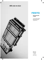
Page 1: ...MPA pneumatics manual Valve terminal with MPA pneumatics Type VT32 Manual 534 241 en 0302NH 665 561 MPA valve terminal ...

Page 2: ......

Page 3: ...726 Esslingen Federal Republic of Germany 2003 Internet http www festo com E Mail service_international festo com The copying distribution and utilization of this document as well as the communication of its contents to others without expressed authorization is prohibited Offenders will be held liable for the payment of damages All rights reserved in particular the right to carry out patent utilit...

Page 4: ...Contents and general instructions II Festo P BE MPA EN en 0302NH ...

Page 5: ...itting removing the inscription label holder 2 13 2 4 Fitting removing the manual override cap optional 2 15 3 Installation 3 1 3 1 Preparing the compressed air 3 4 3 1 1 Operation with non lubricated compressed air 3 4 3 1 2 Operation with lubricated compressed air 3 4 3 2 General notes on connecting the tubing 3 7 3 2 1 Laying the tubing 3 7 3 3 Connecting the MPA valve terminal 3 9 3 3 1 Pilot ...

Page 6: ...ersion 5 1 5 1 General precautionary measures 5 4 5 2 Dismantling the MPA valve terminal 5 5 5 3 Servicing the MPA valve terminal 5 7 5 3 1 Cleaning the large surface mounted silencer 5 7 5 4 Replacing MPA valve terminal components 5 8 5 4 1 Replacing valve plates or blanking plates 5 8 5 4 2 Replacing the electronic modules 5 11 5 4 3 Fitting removing the large surface mounted silencer or the exh...

Page 7: ... 0302NH A Technical appendix A 1 A 1 Technical specifications A 3 A 2 Festo accessories A 10 B Supplementary overview of components B 1 B 1 Overview of valve plates B 3 B 2 Separating the MPA valve terminal from the CPX terminal B 7 C Index C 1 C 1 Index C 3 ...

Page 8: ...Contents and general instructions VI Festo P BE MPA EN en 0302NH ...

Page 9: ...l applications without any modifications by the user Only the conversions or modifications described in the documentation accompanying the product are permitted in faultless technical condition When used together with commercially available compo nents such as actuators the specified limits for pressures temperatures electrical data torques etc must be observed National and local safety regulation...

Page 10: ...bes only the pneumatic components and refers to the valve terminal variants listed in the table below Variants of the MPA valve terminal type VT32 with CPX terminal Information on CPX modules can be found in the manual for the relevant mo dule The following table provides an overview with MP connection Information on the electric electronic components see leaflet with product Table 0 1 Connection ...

Page 11: ...anual CPX field bus node type P BE CPX FB CPX I O modules type P BE CPX EA Valve terminal with MPA pneumatics type P BE MPA CPA pneumatics type P BE CPA Midi Maxipneumatics type P BE MIDI MAXI 03 Contents Instructions on fitting installing commission ing and diagnosing the relevant field bus node Connectiontechniques and instructions on fit ting installing and com missioninginputand output modules...

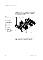
Page 12: ...shown below 1 Exhaust plate or large surface mounted silencer 2 Valve plates 3 Blanking plate 4 End plate 5 Supply unit 6 Sub base 7 Multipin sub base or pneuma tic interface 1 2 3 4 5 6 7 Fig 0 1 Main components of the MPA valve terminal This manual contains the documentation for the valve plates with Ident codes B D E G H J K M N and X see chapter System overview description of components ...

Page 13: ...een the following danger warnings Warning This means that failure to observe this instruction may result in serious personal injury or damage to property Caution This means that failure to observe this instruction may result in personal injury or damage to property Please note This means that failure to observe this instruction may result in damage to property The following pictogram marks passage...

Page 14: ...ns tips and references to other sources of information Accessories Information on necessary or sensible accessories for the Festo product Environment Information on environment friendly use of Festo products Text markings The bullet indicates activities which may be carried out in any order 1 Figures denote activities which must be carried out in the numerical order specified Hyphens indicate gene...

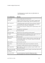
Page 15: ...base with LED and coil management End plate Extreme right hand plate of the MPA valve terminal and extreme left hand plate of the CPX terminal with holes for fitting onto a wall Manual override Manual override Components Common term for pneumatic interface MP sub base exhaust plate large surface mounted silencer pneu sub base supply unit end plate valve plate and blanking plate MP connection Elect...

Page 16: ...ate without valve function for sealing non usd valve locations on sub bases Valve plate Plate with single solenoid valve double solenoid valve or mid position valve Connecting the tubing Connecting the supply lines tubing to the MPA valve terminal Supply unit Unit for additional supply of compressed air to the valve plates e g with several pressure zones Table 0 3 Product specific terms and abbrev...

Page 17: ...Summary of components 1 1 Festo P BE MPA EN en 0302NH Chapter 1 ...

Page 18: ...1 Summary of components 1 2 Festo P BE MPA EN en 0302NH Contents 1 Summary of components 1 1 1 1 The MPA valve terminal 1 4 1 1 1 Overview of variants 1 5 1 1 2 Description of components 1 7 ...

Page 19: ... valve locations the identification code of the valve plates the connecting display and operating elements Further information Information on the electric multipin can be found in the brief description of the MPA valve terminal with multipin connec tion Information on the modules of the CPX terminal can be found in the CPX system manual Information on the electronic modules of the MPA valve ter mi...

Page 20: ...ied with compressed air via the common channels and connections in the basic components Both the exhaust air and pilot exhaust air from the valves are also exhausted via these common channels Further modules for pressure sup ply are also available e g in order to supply pressure zones The MPA valve terminal is fitted with current reduction The rated current of the valve solenoid coils is then redu...

Page 21: ... en 0302NH 1 1 1 Overview of variants MPA valve terminal MPA valve terminal with CPX terminal This MPA valve terminal is available with 4 to max 32 valve locations Maximum 64 valve coils can be actuated Fig 1 1 MPA valve terminal with CPX terminal ...

Page 22: ...with 4 to max 24 valve locations Maximum 24 valve coils can be actuated The electrical connection of the valve solenoid coils is made cen trally via the multipin plug Fig 1 2 MPA valve terminal with multipin connection Sizes of the MPA valve ter minal All MPA valve terminal variants are available with valves in sizes of 10 mm MPA1 ...

Page 23: ...pply con nections exhaust plate or large sur face mounted silencer 3 Valve plates or blanking plates 4 Supply unit with exhaust plate or large surface mounted silencer 5 End plate 6 Sub base with work connections in scription label holders serial linking bus and electronic module with LEDs 7 Sheet seal optional with pressure zone separation 8 Further optional CPX modules Fig 1 3 Components of the ...

Page 24: ...or large surface mounted silencer 2 Electrical linking 3 Valve plates or blanking plates 4 Supply unit with exhaust plate or large surface mounted silencer 5 Right hand end plate 6 Sub base with work connections in scription label holders and electronic module with LEDs 7 Sheet seal optional with pressure zone separation for forming maximum 2 pressure zones Fig 1 4 Components of the MPA valve term...

Page 25: ...rolled Max number of valve locations Remarks CPX terminal 64 32 Two solenoid coils can be controlled per valve location MP connection 24 24 1 With the maximum number of valve locations one solenoid coil can be controlled per valve location 1 If the MPA valve terminal with MP connection also provides valve locations which support control of 2 solenoid coils the maximum possible number of valve loca...

Page 26: ... mid position closed H Valve plate two 3 2 way control side 12 in basic position open control side 14 in basic position closed J Valve plate 5 2 way double solenoid K Valve plate two 3 2 way single solenoid in basic position closed M Valve plate 5 2 way single solenoid N Valve plate two 3 2 way single solenoid in basic position open X Valve plate 3 2 way single solenoid in basic position closed ex...

Page 27: ...minal 1 2 3 5 4 4 6 7 1 Manual override per pilot solenoid turning locking or non locking 2 Exhaust connections 3 5 3 Pilot air exhaust connection 82 84 4 Compressed air connections 1 5 Work connections 2 4 per valve plate 6 Pilot air connection 12 14 7 Manual override cap Fig 1 5 Pneumatic connecting and operating elements of the MPA valve terminal ...

Page 28: ...al with CPX terminal 1 2 3 4 5 6 1 Service interface for handheld etc 2 Field bus connection bus specific 3 LEDs yellow Signal status display of the pilot solenoids red Fault display 4 Identificationfields 5 Power supply connection 6 Earth ground connection Fig 1 6 Electrical connecting and display elements of the MPA valve terminal with CPX terminal ...

Page 29: ...MPA valve terminal with MP connection 1 3 2 4 5 2 1 Sub D multipin plug 2 Inscription label holder with inscription field for ad dresses 3 Earth ground connection 4 Sub D connection 5 LEDs yellow Signal status display of the pilot solenoids Fig 1 7 Electrical connecting and display elements of the MPA valve terminal with MP connection ...

Page 30: ...1 Summary of components 1 14 Festo P BE MPA EN en 0302NH ...

Page 31: ...Fitting 2 1 Festo P BE MPA EN en 0302NH Chapter 2 ...

Page 32: ...General instructions on fitting and dismantling 2 4 2 2 Fitting variants 2 5 2 2 1 Hat rail fitting removal 2 6 2 2 2 Fitting onto removing from a wall 2 10 2 3 Fitting removing the inscription label holder 2 13 2 4 Fitting removing the manual override cap optional 2 15 ...

Page 33: ...the inscription labels the manual override caps Further information Special information on replacing or adding pneumatic compo nents can be found in chapter 5 MPA valve terminal with CPX terminal Information on fitting the MPA valve terminal with CPX terminal can be found in the CPX system manual Information on fitting and dismantling the I O modules can be found in the manual CPX I O modules Info...

Page 34: ...man beings or damage to property Before carrying out installation and maintenance work switch off the following the compressed air supply the operating and load voltage supplies Please note Handle all modules and components of the MPA valve ter minal with great care Please note especially the following The specified torques must be observed Electrostatically sensitive components Do not therefore t...

Page 35: ... wall The multipin sub base or the pneumatic interface and the end plates contain holes for fitting the terminal onto a wall In the case of MPA valve terminals with more than 5 sub bases additional fastening brackets on the supply unit may be necessary see the following instructions and specifications in Appendix A Table 2 1 Methods of fitting the MPA valve terminal Please note Fit the MPA valve t...

Page 36: ...or if it is sub jected to vibration secure the hat rail clamping unit additionally against sliding down and against unintentional loosening or opening with the locking screws see Fig 2 1 item 2 In order to fit the valve terminal onto a hat rail you will require the following mounting kits for MPA valve terminal with MP connection CPA BG NRH This kit consists of 2 M4x10 screws and 2 clamping el eme...

Page 37: ...P sub base 2 in the right hand end plate Table 2 2 Holes for the hat rail clamping unit Fitting Proceed as follows 1 Make sure that the fastening surface can support the weight of the MPA valve terminal weights see Appendix A 2 Fit the hat rail support rail as per EN 50022 35x7 5 width 35 mm height 7 5 mm Make sure there is suffi cient space for connecting the power cables and com pressed air tubi...

Page 38: ... Make sure that the clamping element lies horizontally to the hat rail 1 Hat rail 2 Locking screw of the hat rail clamping unit 3 Clamping el ement of the hat rail clamping unit ÔÔ ÔÔ ÔÔ ÔÔ ÔÔ ÔÔ ÔÔ ÔÔ ÔÔ ÔÔ ÔÔ ÔÔ ÔÔ ÔÔ ÔÔ ÔÔ ÔÔ ÔÔ ÔÔ A B 1 2 3 Fig 2 1 Fitting the MPA valve terminal onto a hat rail 7 Fasten the MPA valve terminal as with the CPX terminal against tilting or sliding by tightening th...

Page 39: ...alve terminal with CPX terminal onto a hat rail can be found in the CPX system manual Dismantling Proceed as follows 1 Loosen the locking screw of the hat rail clamping unit position of the screws see table 2 2 Make sure that the clamping element lies horizontally to the hat rail 2 Swing the MPA valve terminal forwards from the hat rail see Fig 2 3 3 Lift the MPA valve terminal off the hat rail se...

Page 40: ...ping el ement of the hat rail clamping unit ÔÔ ÔÔ ÔÔ ÔÔ ÔÔ ÔÔ ÔÔ ÔÔ ÔÔ ÔÔ ÔÔ ÔÔ ÔÔ ÔÔ ÔÔ ÔÔ ÔÔ 1 A B 2 3 Fig 2 3 Dismantling the MPA valve terminal 2 2 2 Fitting onto removing from a wall The end plates the MP sub base or the pneumatic interface have holes for fitting the terminal onto a wall see table 2 3 ...

Page 41: ...l brackets of type VMPA BG RW The supply units have threaded holes to enable the wall brackets to be fitted In these cases use the additional fastenings for the CPX terminal see instructions in the manual for the CPX sys tem Fitting Proceed as follows 1 Make sure that the fastening surface is flat and can sup port the weight of the MPA valve terminal weights see Appendix A Make sure there is suffi...

Page 42: ...e for M6 screw in the wall bracket op tional 1 1 1 1 2 2 2 2 MPA valve terminal with MP connec tion MP sub base two M4 or M6 screws right hand end plate two M4 or M6 screws 1 Hole for M4 screw 2 Hole for M6 screw Table 2 3 Possibilitiesof fastening the MPA valve terminal Dismantling Proceed as follows 1 Prevent a hanging mounted MPA valve terminal from fal ling down before you loosen it from the f...

Page 43: ... be fitted onto each sub base to enable the valves or work connections to be marked Fitting Proceed as follows Clip the inscription label holders into the grooves in the sub bases see diagram 1 Recess for the in scription label holder in the sub base 2 Inscription label holder 1 2 Fig 2 4 Fitting the inscription label holder ...

Page 44: ...ase 2 Unlock the inscription label holder by using a screwdriver blade width max 3 5 mm to press down the snap hook see diagram 1 Holes for unlock ing the inscrip tion label holder 2 Inscription label holder 1 2 Fig 2 5 Dismantling the inscription label holder 3 Pull the inscription label holder out of the recess in the sub base ...

Page 45: ...f a cap is fitted in the manual override Fitting Proceed as follows 1 Make sure that the relevant manual overrides are in a non actuated state If necessary set locking manual over rides to the basic position see chapter 4 table 4 5 2 Clip the manual override caps into the grooves in the manual overrides see diagram 1 Manual override cap 2 Manual override 1 2 Fig 2 6 Fitting the manual override cap...

Page 46: ...g 2 16 Festo P BE MPA EN en 0302NH Dismantling Proceed as follows Use a suitable screwdriver to lift the manual override caps out of the manual overrides see diagram Fig 2 7 Dismantling the manual override caps ...

Page 47: ...Installation 3 1 Festo P BE MPA EN en 0302NH Chapter 3 ...

Page 48: ... 3 2 General notes on connecting the tubing 3 7 3 2 1 Laying the tubing 3 7 3 3 Connecting the MPA valve terminal 3 9 3 3 1 Pilot control of the valve solenoid coils auxiliary pilot air 3 10 3 3 2 MPA valve terminal with pressure zone separation 3 13 3 3 3 Vacuum low pressure operation 3 18 3 3 4 Connecting the pneumatic tubing 3 19 3 3 5 Connecting the electric cables 3 22 3 4 Address assignment ...

Page 49: ...crew connectors Connecting the power supply Earthing the MPA valve terminal Address assignment of the valves Further information Instructions on connecting the electric components of the MPA valve terminal with MP connection can be found in the leaflet supplied with the product Instructions on the electrical connections can be found in chapter 3 of the CPX system manual Detailed instructions on co...

Page 50: ...ls are used e g HLP oils as per DIN 51524 parts 1 to 3 or corresponding oils on a polyalphaolefine basis PAO the residual oil content must not exceed 5 mg m3 see ISO 8573 1 class 4 You will thereby avoid functional damage to the valves Excessive residual oil cannot be permitted irrespective of the compressor oil as otherwise the basic lubrication will be washed out during the course of time 3 1 2 ...

Page 51: ... oil content in the compressed air will reduce the service life of the valve terminal Use Festo special oil OFSW 32 or the other oils listed in the Festo catalogue as per DIN 51524 HLP32 basic viscosity 32cST at 40 C The additional lubrication must not exceed 25 mg m3 ISO 8573 1 class 5 Make sure that the lubricator setting is correct see fol lowing section You will thereby avoid functional damage...

Page 52: ...ex haust port 5 Let the system run for a short period There must only be a slight yellow colouring on the cardboard If oil drops out this is an indication that too much oil has been used A further indication of excessive lubrication is the colouring or status of the exhaust silencer A distinctly yellow colouring of the filter element or drops of oil on the silencer indicate that the lubricator set...

Page 53: ... valve terminal contain electrostatically sensitive elements The components will be damaged if you touch the contact surfaces of the plug connectors or if you do not observe the regulations for handling electrostatically sensitive components 3 2 1 Laying the tubing If elbow screw connectors or multiple distributors are used the airflow will be reduced slightly Connecting Proceed as follows 1 Push ...

Page 54: ...ed it may perform sudden unexpected movements thereby causing injury to human beings Switch off the compressed air supply before disconnect ing the pneumatic tubing on the MPA valve terminal 1 Loosen the locking screw or press the locking ring of the screw connector 2 Pull out the tubing 3 Replace non required screw connectors with blanking plugs 3 3 Fig 3 2 Disconnecting the tubing ...

Page 55: ... than one supply or exhaust line be used when large volume cylinders are operated at high speeds when several valves are switched simultaneously to the flow position Connections on the following components are available for supplying the valve terminal on the MPA valve terminal with CPX terminal on the pneumatic interface on the supply unit maximum between each sub base optional on the supply unit...

Page 56: ...in ternal auxiliary pilot air Exhaust via large sur face mounted si lencer VMPA FB EPL GU VMPA MP EPL GU sealed connection 12 14 large surface mounted si lencer Pilot control with ex ternal auxiliary pilot air ducted exhaust VMPA FB EPL E VMPA MP EPL E open connection 12 14 exhaust plate Pilot control with ex ternal auxiliary pilot air Exhaust via large sur face mounted si lencer VMPA FB EPL EU VM...

Page 57: ...uxiliary pilot air In this case the auxiliary pilot air is supplied externally via pilot connection 12 14 Please note Use regulated external auxiliary pilot air 3 8 bar Reliable faultless operation of the MPA valve terminal is then possible even with fluctuating operat ing pressure The external auxiliary pilot air is supplied centrally via pilot connection 12 14 on the pneumatic interface or MP su...

Page 58: ... 3 Diagram External auxiliary pilot air as a factor of the operating pressure on valve plates with Ident code N K H and D 1 Pressure of the external auxiliary pilot air at pilot connection 12 14 bar 2 Work range for valves with exter nal auxiliary pilot air 3 Operating pres sure at connec tion 1 bar 0 1 2 3 4 5 6 7 8 9 10 1 2 3 4 5 6 7 8 9 1 0 1 2 3 Fig 3 4 Diagram External auxiliary pilot air as ...

Page 59: ...nel 1 supply channel 1 and exhaust channels 3 and 5 only supply channels 3 and 5 Please note Please note with MPA valve terminals which are operated with internal auxiliary pilot air and which have several pressure zones The auxiliary pilot air is branched centrally from supply connection 1 of the pneumatic interface or the MP sub base for all valve solenoid coils see Figs 3 4 and 3 5 The pressure...

Page 60: ...n 2 Channels 1 3 and 5 blocked 6 Channels 1 3 and 5 blocked 3 Channel 1 blocked 7 Channel 1 blocked 4 Channels 3 and 5 blocked 8 Channels 3 and 5 blocked Table 3 3 Sub base seals identification of the seal variants The following diagrams show as an example the assignment of the supply and exhaust connections to the valve plates on an MPA valve terminal with blocked channels 1 3 and 5 ...

Page 61: ...e outside left of the pneumatic interface for all other pressure zones on the supply unit which lies within the relevant pressure zones The position of the supply unit in the pressure zone left centre or right is optional but two supply units e g of neighbouring pressure zones must not lie next to each other By fitting an additional supply unit within a pressure zone you can supply additional supp...

Page 62: ...rface with supply con nection 1 for presssure zone 1 and pilot connection 12 14 for the com plete valve terminal 2 Pressure zone 1 3 Pressure zone 2 4 Pressure zone 3 5 Supply unit for pressure zone 3 6 Identification of the pressure zone di viding seal projecting flag 7 Supply unit for pressure zone 2 Fig 3 5 Example of MPA valve terminal with CPX terminal and 3 pressure zones ...

Page 63: ...P sub base and for the right hand pressure zone on the supply unit on the outside right see diagram Pilot connec tion 12 14 is on the MP sub base ÖÖÖÖ ÎÎÎÎ ÎÎÎÎ ÖÖÖÖÖ ÖÖÖÖÖ ÎÎÎÎÎ ÖÖÖÖÖ ÎÎÎÎÎ ÎÎÎÎÎ ÖÖÖÖ ÖÖÖÖ ÎÎÎÎÎ 1 2 3 4 5 3 5 3 5 12 14 1 1 1 MP sub base 2 Pressure zone 1 3 Pressure zone 2 4 Supply unit 5 Identification of the pressure zone di viding seal projecting flag Fig 3 6 Example MPA valve ...

Page 64: ...ing pressure for this pressure zone must be set as shown in the diagram in Fig 3 2 The following conditions must be fulfilled before you can op erate your MPA valve terminal at supply connection 1 with vacuum or low pressure between 0 9 3 bar The pilot control of the valve solenoid coils is operated with regulated external auxiliary pilot air The valve terminal is fitted with the following valve p...

Page 65: ...nal Position of the pneumatic connections Please note If the MPA valve terminals are fittted with large surface mounted silencers the exhaust from channels 3 5 82 and 84 will be vented through the surface mounted silencer Connection 82 84 on the supply unit is then sealed with a blanking plug Fit the screw connector or the silencers according to the table below Then connect the pneumatic tubing ...

Page 66: ...ply unit Pilot air exter nal auxiliary pilot air 12 14 M7 Screw connector in the pneumatic inter face or MP sub base Ducted exhaust 3 5 QS10 Screw connector in exhaust plate 2 Ducted pilot exhaust air 82 84 M7 Screw connector in supply unit 2 Work air or vacuum 2 or 4 M7 Screw connector in the sub base 1 Depending on your order the MPA valve terminal may already be fitted with QS screw connectors ...

Page 67: ... Please note In the case of several systems with centrally ducted ex haust air Use non return valves in the common exhaust lines 3 5 or 82 84 in order to prevent functional impairment due to back pressures 1 MPA valve ter minal 1 2 common 3 5 3 central 82 84 4 central 3 5 5 MPA valve ter minal 2 6 common 82 84 1 2 3 4 5 6 6 2 2 Fig 3 8 Common lines with non return valves ...

Page 68: ...ent symbol must be used for supplying PELV networks The devi ce must be earthed to ensure that it functions correctly e g EMC Please note Check within the framework of your EMERGENCY STOP circuit to ascertain the measures necessary for putting your machine system into a safe state in the event of an EMERGENCY Stop e g switching off the operating voltage for the valves and output modules switching ...

Page 69: ...instructions on the MPA valve terminals with CPX terminal in the CPX system manual In this way you can avoid faults due to electromagnetic influences and ensure electromagnetic compatibility in accordance with EMC guidelines 1 1 MPA valve terminal with MP connec tion MPA valve terminal with CPX terminal 1 Earth ground connection Fig 3 9 Earthing the MPA valve terminal Detailed instructions on the ...

Page 70: ...dule orientated A pneumatic module always occupies 8 addresses Counting begins on the valve terminal from left to right Each valve location occupies 2 addresses irrespective of the valve plate or blanking plate which is fitted The following assignment applies Solenoid coil 14 occupies the lower value address solenoid coil 12 occupies the higher value address ...

Page 71: ... Blanking plate 4 Addresses of coil 12 5 Addresses of coil 14 6 Further pneumatic modules 7 First pneumatic module Fig 3 10 Example Address assignment of a MPA valve terminal with CPX terminal and 8 valve locations top view Detailed instructions on addressing the pneumatic modules of the MPA valve terminal with CPX terminal can be found in the manual for the CPX I O modules ...

Page 72: ...occupies the lower value address solenoid coil 12 occupies the higher value address Sum of valve loca tions Valve locations which occupy two addresses each 1 Valve locations which occupy one address each 2 4 all valve locations 8 all valve locations 12 all valve locations 16 valve locations 0 7 valve locations 8 15 20 valve locations 0 3 valve locations 4 19 24 all valve locations 1 Two solenoid c...

Page 73: ...two addresses each 2 Blanking plate on a valve location which occupies two addresses 3 Valve plates on valve locations which occupy one address each 4 Blanking plate on a valve location which occupies one address 5 Addresses of coil 12 6 Addresses of coil 14 Fig 3 11 Example Address assignment of an MPA valve terminal with MP connection and 16 valve locations top view ...

Page 74: ...3 Installation 3 28 Festo P BE MPA EN en 0302NH ...

Page 75: ...Commissioning 4 1 Festo P BE MPA EN en 0302NH Chapter 4 ...

Page 76: ... Before commissioning 4 4 4 1 2 Pressure increase in the complete supply 4 4 4 2 Manual override 4 6 4 3 Checking the valves and the valve actuator combination 4 8 4 4 LED display of the valves 4 14 4 5 Eliminating faults 4 17 4 5 1 Impairment of function 4 17 4 5 2 Operating states of the pneumatic system 4 18 ...

Page 77: ... MPA valve terminal The following in particular belong here Checking the valve functions Operating the manual override Checking the valve actuator combination Eliminating faults The assignment of the LEDs Further information Commissioning the CPX terminal is described in the appropri ate manual for the CPX field bus node ...

Page 78: ...ntly under stress Please observe the following instructions for building up pressure in the complete supply 4 1 2 Pressure increase in the complete supply Warning If the build up in pressure of the auxiliary pilot air is too slow or delayed this may cause the actuators to perform sudden unexpected movements under the following condi tions If the compressed air is switched on with a safety start up...

Page 79: ...ignal being pres ent The slow increase in pressure of the complete supply does not then affect the actuator The actuator would react suddenly e g a cylinder would extend or retract depending on the valve function 1 4 2 5 3 14 12 1 2 1 12 14 12 14 3 82 84 2 1 Externally supplied auxiliary pilot air 3 to 8 bar branched in front of the safety start up valve 2 Safety start up valve slow build up of pr...

Page 80: ...slow Table 4 1 Effects of slow start up pressurization 4 2 Manual override You should use the manual override especially when commis sioning the pneumatic system in order to check the function and operation of the valve or the valve actuator combination By actuating the manual override you can switch the valve without an electric signal You only need to switch on the compressed air supply The manu...

Page 81: ...ation if a cap is fitted in the manual override The assignment of the manual override actuations to the valve solenoid coils is as follows 1 3 5 7 9 0 2 4 6 8 10 12 14 16 17 18 19 20 21 22 23 11 13 15 1 2 1 Manual override for valve solenoid coils 12 2 Manual override for valve solenoid coils 14 Fig 4 2 Position of the manual overrides top view ...

Page 82: ... should be commissioned as follows Commissioning variants Activity Preliminarytest of the pneuma tic tubing Testing the valve actuator com bination by means of the manual override Complete commissioning of the complete system Installing and connecting the complete system Program control via PLC indu strial PC Table 4 3 Commissioning variants Commissioning the pneumatic components by means of the m...

Page 83: ...on the power supply During commissioning manual override functions which are in the switched state can cause actuators to perform sudden unexpected movements These movements can cause injury to human beings and damage to property Make sure that all manual override actuations are in their basic positions You will thereby avoid undefined switching states of the valves Proceed as follows Warning Befo...

Page 84: ...the manual override Use a screwdriver blade width max 2 5 mm for actuat ing the manual override Actuate the manual override with only max 25 N 3 With the locking function of the manual override make sure after testing the valves that all manual override actuations are in their basic positions 4 Switch off the compressed air supply after checking the valves ...

Page 85: ... to the switching position Hold the plunger of the manual over ride pressed down remains in the switch position Release the plunger the spring resets the plunger of the manual override to the starting position moves back to the basic position not with double solenoid valve Ident code J Table 4 4 Operating the non locking manual override Please note A valve which has been switched by an electric si...

Page 86: ...idth 2 5 mm to press down the plunger of the manual override until the valve switches Then turn the plunger in a clock wise direction as far as possible The valve moves to the switching position Leave the plunger in position remains in the switch position Then turn the plunger in an anti clockwise direction as far as poss ible Then release the plunger moves back to the basic position not with doub...

Page 87: ... manual override functions which are in the switched state can cause actuators to perform sudden unexpected movements These movements can cause injury to human beings and damage to property Before commissioning bring the manual override actua tions into the basic position again ...

Page 88: ...ow shows the position of the LED and the manual override for the relevant valve solenoid coil 1 LED and manual override for valve solenoid coil 12 2 LED and manual override for valve solenoid coil 14 12 12 12 12 12 12 12 12 14 14 14 14 14 14 14 14 14 14 14 14 2 1 2 1 Fig 4 3 Assignment of LEDs and manual override to the valve solenoid coils ...

Page 89: ... basic position logical 1 signal present logical 1 but compressed air supply not OK or pilot exhaust blocked or servicingrequired lights up red in the starting phase for ap prox 2 seconds duringoperation Test phase when power supply has been switched on Operating voltage of the valves lies below the permitted tolerance range 18 30 V DC Module fault e g undervoltage of the electronic module see man...

Page 90: ...of the valve Meaning out basic position logical 0 no signal yellow alight switch position or basic position logical 1 signal present logical 1 but load voltage of the valves lies below the per mitted tolerance range 18 V 30 V DC compressed air supply not OK or pilot exhaust blocked or servicingrequired Table 4 7 Meaning of the LED display MPA valve terminal with MP connection ...

Page 91: ...s Check the tubing fitting The valve or the pneumatic system does not react as expected not react Check the tubing Check the electric cables Bring the locking manual override into the basic position After switching on again check the operating pressure if necessary for each pressure zone Set operating pressure in accordance with in structions in chapter 3 In the case of valve terminals which are o...

Page 92: ...rally ducted exhaust are used two or more pressure zones limiting the pressure zones by means of sheet seals with blocked channels subsequent conversion possible see chapter 5 vacuum or low pres sure operation externally supplied regulated auxi liary pilot air 3 8 bar controller can only be operated with pressure between 3 8 bar vacuum low pressureoperation not with 3 2 way valves EMERGENCY STOP o...

Page 93: ...Maintenance and conversion 5 1 Festo P BE MPA EN en 0302NH Chapter 5 ...

Page 94: ...er 5 7 5 4 Replacing MPA valve terminal components 5 8 5 4 1 Replacing valve plates or blanking plates 5 8 5 4 2 Replacing the electronic modules 5 11 5 4 3 Fitting removing the large surface mounted silencer or the exhaust plate 5 14 5 4 4 Replacing the sub base 5 14 5 5 Converting the MPA valve terminal 5 18 5 5 1 Conversion to internal or external pilot air 5 18 5 5 2 Converting the MPA valve t...

Page 95: ...nted silencer sub bases The following activities are also described adding pressure zones converting the valve terminal to internal or external auxili ary pilot air Further information MPA valve terminal with CPX terminal Information on fitting removing components and on the elec trical connections can be found in the CPX system manual MPA valve terminal with multipin connection Instructions on co...

Page 96: ...rating and load voltage supplies Please note Handle all modules and components of the valve terminal with great care Note especially the following when fitting components Screws must be fitted accurately otherwise threads will be damaged Screws must be screwed in only by hand Place the screws so that the self cutting threads are used The specified torques must be observed Screw connections must be...

Page 97: ...e placed or removed valve plates or blanking plates electronic modules exhaust plates or large surface mounted silencer Loosening the electrical connections Connecting variants Procedure CPX terminal Instructions on loosening the electrical connections can be found in the CPX system manual MP connection Loosen and remove the fastening screws of the sub D multipin plug Table 5 1 Loosening the elect...

Page 98: ...man beings Switch off the compressed air supply before disconnect ing the pneumatic tubing on the MPA valve terminal Proceed as follows 1 Mark all pneumatic tubing 2 Press down the blue clamping ring 1 of the screw con nector e g with a screwdriver 3 Pull the pneumatic tubing away from the screw connector 1 Fig 5 1 Removing the tubing Dismantling the MPA valve terminal The procedure for dismantlin...

Page 99: ...rve the safety regulations for easily inflammable cleaning agents In this way you can ensure that the large surface mounted silencer functions correctly and that the valves operate correctly Proceed as follows 1 Loosen the 6 fastening screws of the surface mounted silencer and remove it from the basis components 2 Clean the surface mounted silencer with benzine or paraf fin 3 Check the seal betwee...

Page 100: ...sion work 5 4 1 Replacing valve plates or blanking plates Please note The sub bases of the MPA valve terminal with MP connec tion support the control of one or two solenoid coils de pending on the equipment fitted total number of valve locations see chapter 3 table 3 5 Dismantling Proceed as follows Use a narrow screwdriver to loosen the fastening screws and remove the components from the sub base...

Page 101: ...ed 3 Make sure that the seal is seated correctly The cord seal between the sub base and the component must be seated in the groove in the component sitzen The ring seals between the electronic module and the component are conical They must be fitted onto the guide pin of the component so that the cone fits easily into the appropriate recess in the electronic module when it is mounted alignment see...

Page 102: ...Valve plate or blanking plate 3 Cord seal 4 2 conical seals per valve plate or blanking plate observe the alignment 5 Sub base 6 Electronic module 1 2 3 4 5 6 Fig 5 3 Fitting valve plates or blanking plates 4 Place the component on the sub base 5 Screw the component at first only slightly and then tighten with 0 25 Nm 20 ...

Page 103: ...wer supply before removing the elec tronic modules Do not therefore touch any contact surfaces Observe the regulations for handling electrostatically sensitive components Discharge yourself electrostatically before fitting or re moving components in order to protect the components against discharges of static electricity Before removing the electronic module you must first remove all valve plates ...

Page 104: ...g off the valve power supply at all poles You must observe the instructions in the manual for the CPX I O modules if you wish to fit an electronic module of a different type Recommendation Replace only with electronic modules of the same type The following types are available Type VMPA1 FB EMG 8 electronic module with 8 outputs and electrical isolation of the supply voltages Type VMPA1 FB EMS 8 el...

Page 105: ...th 0 25 Nm 3 Then fit the valve plates or blanking plates see section Fitting valve plates or blanking plates MPA valve terminal with MP connection Caution Replace an electronic module only by an electronic module of the same type You can then avoid problems in controlling the valve solenoid coils and damage to the electrical contacts The following types are available type VMPA1 MP EMS 4 Electroni...

Page 106: ...urface mounted si lencer or exhaust plate 4 Fasten the large surface mounted silencer or exhaust plate only with the original screws Tighten these screws in diagonally opposite sequence with max 0 65 Nm ex haust plate or 1 0 Nm large surface mounted silencer 5 4 4 Replacing the sub base Dismantling Proceed as follows 1 Loosen the electrical and pneumatic connections and re move the MPA valve termi...

Page 107: ...s of the sub bases which you wish to dismantle The sub bases are now held to gether only by the electrical linking or by the bus ÖÖ ÖÖ ÖÖ ÖÖ Fig 5 4 Position of the screw connectors of the sub bases and the right hand end plate 4 Pull the relevant sub base away from the neighbouring sub bases ...

Page 108: ...llows 1 Make sure the seals are not damaged Replace the seals if they are damaged Place the flat seal onto the guide pin of the sub base 1 Guide pins 2 Sheet seal op tional with pres sure zone separ ation 2 1 1 Fig 5 5 Fitting the sub base 2 Place the new sub base onto the sheet seal ...

Page 109: ... shown in the dia gram at first slightly and then with 1 3 Nm 1 2 2 1 3 Fig 5 6 Screw connectors of the sub bases 4 Mount the MPA valve terminals onto the fastening surface see chapter 2 Fitting onto a wall or Fitting onto a hat rail 5 Then fit the pneumatic and electrical connections see chapter 3 Installation connecting the MPA valve ter minal ...

Page 110: ...es Adding valve locations sub bases 5 5 1 conversion to internal or external pilot air Depending on the pneumatic interface or multipin sub base fitted pilot control of the valve solenoid coils can be carried out with internal or external auxiliary pilot air Please note Mixed operation of the MPA valve terminal with internal and external auxiliary pilot air is not intended Irrespective of the avai...

Page 111: ...MP sub base and is open The auxiliary pilot air is supplied externally via pilot connection 12 14 Pressure zone separation is permitted Unused connections must be sealed For operating the pilot control with internal auxiliary pilot air Pilot connection 12 14 is not marked on the pneumatic interface or on the MP sub base and is closed The auxiliary pilot air is branched internally from con nection ...

Page 112: ...t air Exhausting via large surface mounted si lencer VMPA FB EPL GU VMPA MP EPL GU connection 12 14 sealed Large surface mounted si lencer Pilot control with ex ternal auxiliary pilot air Ducted exhaust VMPA FB EPL E VMPA MP EPL E connection 12 14 open exhaust plate Pilot control with ex ternal auxiliary pilot air Exhausting via large surface mounted si lencer VMPA FB EPL EU VMPA MP EPL EU connect...

Page 113: ...g number of pressure zones depending on the connecting vari ant Electrical connection variant CPX terminal MP connection Pressure zones 1 8 1 2 Table 5 4 Number of pressure zones The pressure zones are implemented by means of special sheet seals which separate the following channels only the supply channel 1 supply channel 1 and exhaust channels 3 and 5 only exhaust channels 3 and 5 ...

Page 114: ...nes see dia gram 1 2 3 5 6 7 8 4 MPA valve terminal with large surface mounted silencer exhaust plates 1 Channels 1 3 and 5 open 5 Channels 1 3 and 5 open 2 Channels 1 3 and 5 blocked 6 Channels 1 3 and 5 blocked 3 Channel 1 blocked 7 Channel 1 blocked 4 Channels 3 and 5 blocked 8 Channels 3 and 5 blocked Table 5 5 Sub base seals identification of the seal variants ...

Page 115: ... VMPA DP A supply plate with exhaust plate or large surface mounted silencer VMPA FB SP or VMPA FB SPU Dismantling Proceed as follows 1 Loosen the electrical and pneumatic connections and re move the MPA valve terminal from the fastening surface see section Dismantling the MPA valve terminal in this chapter 2 Place the MPA valve terminal on a flat working surface 3 Loosen the sub base at the point...

Page 116: ...tion Fitting sub bases 3 Mount the MPA valve terminals onto the fastening surface see chapter 2 Fitting onto a wall or Fitting onto a hat rail 4 Then fit the pneumatic and electrical connections see chapter 3 Installation connecting the MPA valve ter minal The following diagram shows the layout of pressure zones using as an example an MPA valve terminal with CPX ter minal ...

Page 117: ... Supply unit with connection 1 for supplying compressed air to the 3rd pressure zone 5 Identifying the sheet seal with pressure zone separation 6 Supply unit with connection 1 for supplying compressed air to the 2nd pres sure zone 7 Pneumatic interface with connection 1 for supplying compressed air to the 1st pressure zone Fig 5 7 Example of MPA valve terminal with CPX terminal and 3 pressure zone...

Page 118: ...zone via a supply plate which is situ ated next to the right hand end plate Dismantling Proceed as follows 1 Loosen the electrical and pneumatic connections and re move the MPA valve terminal from the fastening surface see section Dismantling the MPA valve terminal in this chapter 2 Place the MPA valve terminal on a flat working surface 3 Remove all valve plates and blanking plates and then all el...

Page 119: ... fit the pneumatic and electrical connections see chapter 3 Installation connecting the MPA valve ter minal 5 5 3 Adding valve locations The MPA valve terminal with MP connection is available with 4 8 12 16 20 or 24 valve locations With this valve terminal variant it is not intended that the number of valve locations be increased or reduced Adding valve locations You can easily adapt the MPA valve...

Page 120: ...M 4 valve plates or blanking plates per sub base VMPA M1H Table 5 6 Valve location extension Dismantling Proceed as follows 1 Loosen the MPA valve terminal from the fastening surface see section Dismantling the MPA valve terminal 2 Dismantle the sub base or the supply plate at the point where you wish to extend the valve terminal see section Dismantling sub bases ...

Page 121: ...tions see section Fitting valve plates or blank ing plates 3 Fit the MPA valve terminal onto the fastening surface see chapter 2 Fitting onto a wall or Fitting onto a hat rail 4 Then fit the pneumatic and electrical connections see chapter 3 Installation connecting the MPA valve ter minal Please note If a sub base is inserted between existing sub bases the address assignment of all the valves to t...

Page 122: ...5 Maintenance and conversion 5 30 Festo P BE MPA EN en 0302NH ...

Page 123: ...Technical appendix A 1 Festo P BE MPA EN en 0302NH Appendix A ...

Page 124: ...A Technical appendix A 2 Festo P BE MPA EN en 0302NH Contents A Technical appendix A 1 A 1 Technical specifications A 3 A 2 Festo accessories A 10 ...

Page 125: ...xhaust plate on supply unit Large surface mounted silencer on supply unit Fastening of the sub base Multipinconnection Support bracket on the supply unit 0 25 Nm 20 0 65 Nm 1 0 Nm 1 3 Nm 0 65 Nm 1 Nm Materials Sub base supply unit valve and end plates electronic modules MP connection seals Al POM polycarbonate Polyamide 6 elastomer NBR Weight in g basic weight per pneumatic module 4 valve plates p...

Page 126: ...P connection and more than 5 sub bases severity class 1 MPA valve terminal with CPX terminal and up to 5 sub bases severity class 2 up to 6 sub bases with additional fastenings wall bracket on every 2nd 4th supply unit severity class 2 6 or more sub bases without additional fastenings severity class 1 3 Explanations on the severity classes see following table Table A 2 Vibration and shock Severity...

Page 127: ...l VG 32 ornon lubricated vacuum Design Valve plates with piston spool valves Pilot control with auxiliary pilot air branched inter nally from connection 1 with external auxiliary pilot air Pressure range Valve location Ident code D N K H X M J B G E at connection 1 12 14 3 8 bar Valve location Ident code B E G J M and X at connection 1 0 9 10 bar Valve location Ident code D H N K at connection 1 3...

Page 128: ... 5 6 7 8 9 1 2 3 Fig A 1 Diagram Pilot pressure with external auxiliary pilot air for valve plates with Ident code N K H and D 1 Pilot pressure 12 14 bar 2 Work range for valves with exter nal auxiliary pilot air 3 Work pressure P1 bar 0 1 2 3 4 5 6 7 8 9 10 1 2 3 4 5 6 7 8 9 1 0 1 2 3 Fig A 2 Diagram Pilot pressure with external auxiliary pilot air for valve plates with Ident code M J B E G and X...

Page 129: ...es 1 x 3 2 way valve closed 5 2 way valve single solenoid 5 2 way valve double solenoid 5 3 way valve pressurized 5 3 way valve closed 5 3 way valve exhausted 1 2 or 1 4 230 300 230 280 255 360 360 300 195 320 240 2 3 5 or 4 3 5 230 300 310 305 295 360 360 270 320 240 180 Valve switching times in ms measuring method 0 10 as per FN942032 On switch over Off D N K H X M J B G E 2 x 2 2 way valves all...

Page 130: ... Load voltage supply for valves VVEN Rated voltage Internal current consumption at 24 V internal electronics Diagnostic message undervoltage VOFF load voltage outside function range MPA valve terminal with CPX terminal 24 V DC 25 typ 13 20 mA 24 V DC 25 typ 8 mA not electrically isolated electronic module type VMPA1 FB EMS 8 typ 25 mA electrically isolated electronic module type VMPA1 FB EMG 8 17 ...

Page 131: ... specifications for the electric components of the MPA valve terminal with MP connection are enclosed with the product Technical specifications for the electronic module of the MPA valve terminal with CPX terminal can be found in the manual for the CPX I O modules ...

Page 132: ...ction of manual override accessible Hat rail fitting kit Inscription label holder Additional fastening bracket for wall fitting VMPA1 HBV VMPA1 HBT CPX10 14 BG NRH VMPA1 ST 1 4 VMPA BG RW MPA valve terminal with MP connection Ready to use multipin cable for terminals with 4 valve locations for terminals with 8 24 valve locations Multipinsocket VMPA KMS1 8 VMPA KMS1 24 Table A 7 Accessories for the...

Page 133: ...Supplementary overview of components B 1 Festo P BE MPA EN en 0302NH Appendix B ...

Page 134: ...entary overview of components B 2 Festo P BE MPA EN en 0302NH Contents B Supplementary overview of components B 1 B 1 Overview of valve plates B 3 B 2 Separating the MPA valve terminal from the CPX terminal B 7 ...

Page 135: ...de 14 or coil 14 They are not logic designations Valve plates with 2 2 way valves 82 84 12 14 1 4 2 12 14 Ident code D Function Two single solenoid 2 2 way valves basic position closed Table B 1 Valve plates with 2 2 way valves Valve plates with 3 2 way valves 82 84 12 14 5 3 1 4 2 12 14 Ident code K Function Two single solenoid 3 2 way valves basic position closed 82 84 12 14 5 3 1 4 2 12 14 Iden...

Page 136: ... and on control side 12 a single solenoid 3 2 way valve basic position open 82 84 12 14 3 2 4 14 Ident code X Function Valve plate 3 2 way single solenoid basic posi tion closed external pressure supply Please note Number of assigned outputs on an MPA valve terminal with MP connection The number of outputs which are assigned to this valve depends on the valve location see table 3 3 Table B 2 Valve...

Page 137: ...tion One single solenoid 5 2 way valve Please note Number of assigned outputs on an MPA valve terminal with MP connection The number of outputs which are assigned to this valve depends on the valve location see table 3 3 82 84 12 14 5 3 1 4 2 12 14 Ident code J Function One 5 2 way valve double solenoid Table B 3 Valve plates with 5 2 way valves ...

Page 138: ... 84 12 14 5 3 1 4 2 12 14 Ident code B Function 5 3 way valve mid position pressurized 82 84 12 14 5 3 1 4 2 12 14 Ident code G Function 5 3 way valve in mid position blocked 82 84 12 14 5 3 1 4 2 12 14 Ident code E Function 5 3 way valve in mid position exhausted Table B 4 Valve plates with 5 3 way valves ...

Page 139: ...am 1 CPX terminal 2 Pneumatic inter face 3 MPA valve ter minal 1 2 3 Fig B 1 Pneumatic interface Dismantling Proceed as follows 1 Loosen the electrical and pneumatic connections and re move the MPA valve terminal from its fastening surface see chapter 5 Dismantling the MPA valve terminal 2 Loosen the fastening screws between the pneumatic inter face and the MPA sub base in the sequence 1 2 3 see F...

Page 140: ...as follows 1 Check the seal between the pneumatic interface and the MPA valve terminal for damage If necessary use a new seal 2 Push the MPA valve terminal together with the CPX ter minal Make sure that the seal and the MPA valve ter minal are correctly positioned in relationship to the CPX terminal 3 Insert the fastening screws in the appropriate holes Tighten the screws in the sequence specified...

Page 141: ...ten the CPX terminal onto the mounting surface see CPX system manual 5 Carry out the electrical and pneumatic connections of the CPX terminal Information on this can be found in the electrics section of the CPX system manual in the pneumatics section in chapter 3 of this manual ...

Page 142: ...B Supplementary overview of components B 10 Festo P BE MPA EN en 0302NH ...

Page 143: ...Index C 1 Festo P BE MPA EN en 0302NH Appendix C ...

Page 144: ...C Index C 2 Festo P BE MPA EN en 0302NH Contents C Index C 1 C 1 Index C 3 ...

Page 145: ...lly 3 11 C Common tubing 3 21 Compressed air requirements 3 4 Connections electrical MPA valve terminal with CPX terminal 1 12 electrical terminal with multipin connection 1 13 identifier 3 20 pneumatic 1 11 size 3 20 Current consumption A 8 D Designated use VII Disconnecting the tubing 3 8 Display elements MPA valve terminal with CPX terminal 1 12 MPA valve terminal with multipin connection 1 13 ...

Page 146: ...t air 3 11 conversion 5 18 F Fastening accessories Hat rail 2 7 Fitting onto a wall 2 10 Fitting tubing 3 8 Fitting variants fitting onto a hat rail 2 5 fitting onto a wall 2 5 Flow rates A 7 H Hat rail clamping unit 2 8 Fitting 2 6 I Impairment of function 4 17 Important user instructions XI Internal pilot air 3 10 conversion 5 18 ...

Page 147: ... locking 4 12 non locking 4 11 types 4 6 Manuals on the MPA valve terminal with CPX terminal IX Micro valves 1 6 Mounting kit for hat rail fitting 2 6 MP connection 1 13 MPA valve terminal Address assignment of the outputs 3 24 components 1 7 1 8 earthing the valve terminal 3 23 loosen the CPX terminal B 7 overview of variants 1 5 sizes 1 6 Valve plates X N Non return valve 3 21 Notes on the use o...

Page 148: ...on of the LEDs 4 14 Power supply load voltage supply for the valves A 8 operating voltage supply for the electronics A 8 Pressure range A 5 Pressure zones 3 13 4 18 common pneumatic line 3 13 conversion 5 21 Protection class A 3 R Removing the blanking plate 5 8 Removing the exhaust plate 5 8 Replacing the sub base 5 14 Replacing valve plates 5 8 ...

Page 149: ...External pilot air 3 11 external pilot air 3 11 internal pilot air 3 10 Support rail 2 6 T Target group VII Text markings XII Tightening torques A 3 Tubing variants 5 6 V Vacuum operation 3 18 4 18 Valve locations adding 5 27 Valve locations 1 9 Valve plates X 1 10 Identification code 1 10 overview B 3 Valve switching times A 7 Vibration A 4 ...

Page 150: ...C Index C 8 Festo P BE MPA EN en 0302NH ...

Reviews: