Festo — VTSA-F-CB — 2021-06a
Modification
79
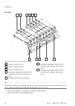
2. Remove components.
Assembly
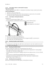
1. Replace damaged seals.
2. Place a new component on the valve position or on a mounted component.
3. Screw in the retaining screws of the new component.
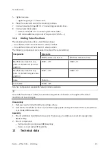
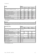
4. Tighten the retaining screws of the new component:
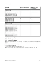
Component
Width
18 mm
26 mm
42 mm
52 mm
Valves
Width across
flats
2.5
3.0
4.0
5.0
Tightening
torque
1.0 Nm ± 10%
2.0 Nm ± 10%
3.0 Nm ± 20%
6.5 Nm ± 20%
Vertical stacking components
Width across
flats
2.0
2.5
3.0
4.0
Tightening
torque
1.0 Nm ± 10%
2.0 Nm ± 10%
3.0 Nm ± 15%
5.0 Nm ± 20%
5. Reinstall disassembled components.
11.1.4
Replacing the manifold sub-bases or right-hand end plate
The use of non-permitted manifold sub-bases will cause irreparable damage to the valve terminal.
• Only use manifold sub-bases with a black electrical manifold module.
• Mount only pilot air switching valves to the manifold sub-base of the pilot air switching valve.
The number of manifold sub-bases with which the valve terminal can be equipped depends on:
• Type of manifold sub-base
• Electrical connection
Address assignment
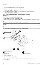
Disassembly
1. Disconnect electrical and pneumatic connections.
2. Remove the valve terminal from the mounting surface
è
Assembly instructions VABV-S6-1Q-... .
3. Place valve terminal on a flat working surface.
4. Remove the screws of the component and the adjacent component.

