


7
Commissioning
Note
• Commissioning only by qualified personnel.
• When incompressible media (e.g. neutral water) are used, switching the valve
causes pressure surges in the tubing system. Prior to commissioning, check
the compatibility of the devices in the system to avoid damaging them. If
necessary, adjust your application parameters.
• Observe the information on the rating plate.
• Start up the solenoid valve only when it is completely assembled and installed.
• Check the connection points for leaks.
• Prior to commissioning, check for compliance with the operating conditions and
the permissible limit values (e.g. operating medium, operating pressure, differ-
ential pressure, voltage and frequency, ambient temperature and media temper-
ature
Î
Technical data).
8
Operation
• Observe the operating conditions.
• Always observe the permissible limit values.
Warning
Danger of burning on hot surfaces.
The surface temperature of the solenoid valve can exceed 75 °C.
• Do not touch the solenoid valve.
9
Dismantling
Warning
Danger of injury due to hot media under pressure.
The media in the piping system and the solenoid valve can be hot and can be
under pressure.
• Allow the solenoid valve and pipelines to cool and depressurise them.
Note
The solenoid valve may be dismantled only by qualified personnel.
1. Depressurise the pipeline.
2. Switch off the voltage.
3. Completely drain the pipeline and valve.
– Allow the solenoid valve and pipeline to cool off.
– Make sure that no one is in front of the outlet opening.
– Catch escaping media in a suitable container.
4. Remove the solenoid valve from the pipeline (unplug the electrical plug con-
nector, detach the mounting bracket and unscrew the fittings).
10
Changing the solenoid coil
The solenoid coil can be changed for repairs.
Warning
Danger of injury from hot surfaces.
The surface temperature of the solenoid valve can exceed 75 °C.
• Let the solenoid valve cool off.
Dismantling:
1. Switch off the voltage.
2. Disconnect the electrical plug connector.
3. Undo the knurled nut and remove the solenoid coil from the armature guiding
tube.
Mounting:
1. Push the O-ring and solenoid coil over the armature guiding tube.
2. Secure the solenoid coil with the O-ring and knurled nut.
– Torque for tightening the knurled nut: finger-tight (about 1...1.5 Nm).
11
Service and maintenance
• Check the solenoid valve for leakage at least every 6 months.
• Check the functioning of the solenoid valve at least every 6 months.
• Regularly clean the outside of the valve with a soft cloth. The permissible
cleaning agent is soap suds.
12
Eliminating malfunctions
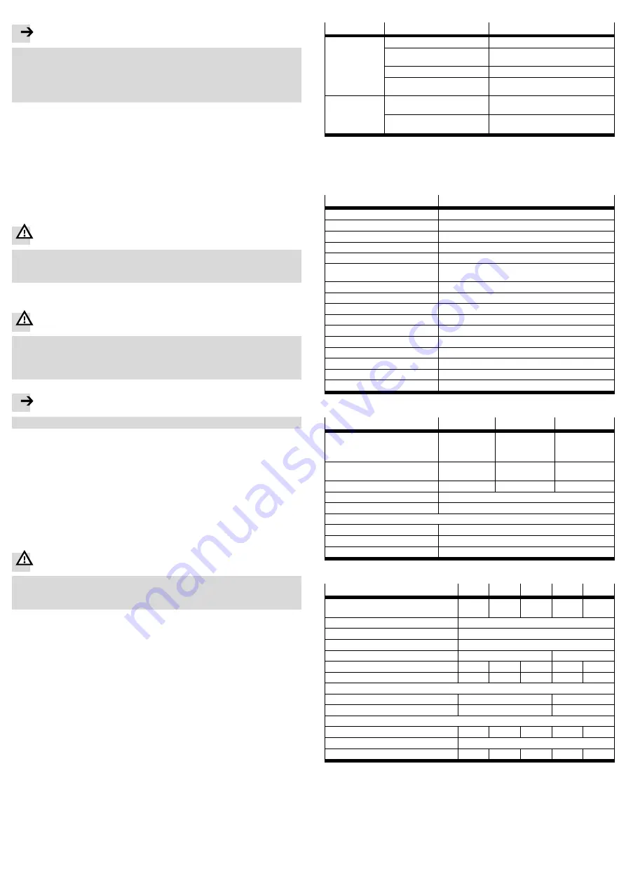
Malfunction
Possible cause
Remedy
Solenoid valve
not closing
Solenoid valve is defective.
• Replace the solenoid valve.
Flow direction is incorrect
• Install the solenoid valve in accord-
ance with the flow arrow
Nominal voltage is still applied
• Check electrical connection.
Differential pressure too low
• Make sure the specified minimum
differential pressure is supplied.
Solenoid valve
does not open
Solenoid coil or solenoid valve is
defective.
• Replace the solenoid coil.
• Replace the solenoid valve.
Nominal voltage interrupted or
not sufficient
• Check voltage.
Fig. 3
• Send defective solenoid coils to Festo's repair service. For information about
spare parts and auxiliary equipment see www.festo.com/spareparts.
13
Technical data
General
VZWP-L-M22C-...-P4-...
Valve function
2/2-way, closed, monostable
Design
Solenoid valve, servo controlled
Actuation type
Electrical
Mounting position
Solenoid preferably vertical
Sealing principle
Soft
Operating medium
– Neutral, gaseous and fluid media
– No chemically unstable gases
Direction of flow
Non-reversible
Viscosity
[mm
2
/s]
š
22
Grade of filtration
[
μ
m]
40
Temperature of medium
[°C]
–10...+80
Ambient temperature
[°C]
–10...+35
Protection class
IP65 as per DIN EN 60529
Degree of contamination
3 as per IEC 60664-1
Attachment type
In-line installation
Valve housing material
Brass
Seal
NBR, FKM
Fig. 4
Electrical data
VZWP-...1-...
VZWP-...2A-...
VZWP-...3A-...
Nominal voltage
– DC voltage
– AC voltage (50...60 Hz)
[V DC]
[V AC]
24 (±10%)
–
–
110 (±10%)
–
230 (±10%)
Rated output
[W]
[VA]
6.8
–
7.5
–
10.5
Surge resistance
[kV]
–
2.5
4.0
Duty cycle
100% (continuous duty)
Electrical connection
Device plug per DIN EN 175301-803, format A
Connecting cable
– Cable cross-section
[mm
2
]
0.75...1.5
– Cable diameter
[mm]
5...9
– Cable entry thread
M20x1.5
Fig. 5
Port size
[
˝
]
¼
y
½
¾
1
Pipe thread per DIN ISO 228
Pipe thread per ANSI B 1.20.1
G
¼
N
¼
G
Å
N
Å
G
½
N
½
G
¾
N
¾
G1
N1
Max. operating pressure
[bar]
40
Overload pressure
[bar]
45
Min. differential pressure
[bar]
0.5
Nominal size (DN)
[mm]
13
25
Standard nominal flow rate
[l/min]
1600
2100
2650
8750
12250
Flow factor K
v
[m
3
/h]
1.5
2.0
2.5
8.2
11.5
Switching times for gaseous media
1)
– On
[ms]
100
130
– Off
[ms]
250
300
Tightening torques
– Pipe connection
[Nm]
35
60
105
200
350
– Mounting of solenoid coil
[Nm]
2
Weight
[g]
600
575
550
1500
1400
1)
Depending on the viscosity, longer switching times with fluid media
Fig. 6


