background image

7

Assembly

CAUTION!

Risk of injury due to falling product.

Make sure the mounting surface is sufficiently strong to absorb the maximum forces.

Only use suitable mounting components.

Secure the screw connections.

Observe the information on mounting components in the respective documentation

è

 1.1 Applicable documents.

1. Assemble the cylinder DSBG and accessories as follows.

Assemble the DSBG backlash-free and free from transverse loads.

To prevent friction, ensure parallelism with the guide unit.

If possible, use a self-aligning rod coupler to balance the angular and radial backlash.

2. Mount the proximity sensor SMT as a reference sensor to the displacement encoder DNCI. The

proximity sensor is needed for referencing of the displacement encoder. Information on referen-
cing 

è

 1.1 Applicable documents.

Attach the proximity sensor near the lower end position of the DNCI. Tightening torque:

£

 0.6 Nm

3. Assemble the displacement encoder DNCI backlash-free and parallel to the cylinder DSBG.

There must be a secure connection between the DSBG piston rod and DNCI piston rod.

Choose suitable accessories in accordance with the installation situation.

4. Assemble the valve unit VPCB.
5. Connect the valve unit VPCB with the cylinder DSBG. There are two options for this:

Connect the valve unit VPCB directly with the cylinder DSBG using a double nipple.
Internal diameter: 

³

 8 mm

Connect the valve unit VPCB with a pipe or a suitable hydraulic hose 

£

 300 mm with the cylin-

der DSBG.

A connection with the aid of tubing is not permitted.

6. Assemble the control element VAOH in the appropriate place. Tightening torque: 

£

 10 Nm

7. Assemble the balancer kit CECC-D-BA in accordance with local conditions and in compliance with

the degree of protection.

Assembly

9

Festo — YHBP-1 — 2018-11

Summary of Contents for YHBP-1

Page 1: ...8088702 YHBP 1 Balancer kit 8088702 2018 11 8088704 Instructions Assembly Installation...

Page 2: ...Translation of the original instructions 2 Festo YHBP 1 2018 11...

Page 3: ...4 Service 6 5 Product overview YHBP 7 5 1 Scope of delivery 7 5 2 Function 8 6 Transport 8 7 Assembly 9 8 Installation 10 8 1 Interfaces of valve unit VPCB T22 10 8 2 Pneumatic installation 11 8 3 In...

Page 4: ...Instruction manu al Control element VAOH P15 H13 Operation Instruction manu al Valve unit VPCB T22 Operation installation Instruction manu al Connector SET VABS P15 S B6 Assembly Description Controlle...

Page 5: ...ey Data Matrix Code of the product 2 Download documents from the Festo Support Portal by entering the order ID product key Data Matrix Code www festo com sp 3 Print out documents and keep together wit...

Page 6: ...d and the manufacturer is not liable for damages 2 3 Foreseeable misuse Never use the product as follows With unauthorised modifications or alterations to the product With load limits exceeded In an i...

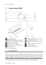
Page 7: ...rol element VAOH 11 Tubing not in scope of delivery Fig 1 Product overview YHBP 5 1 Scope of delivery The kit only contains individual components that can be used for building a servo pneumatic balanc...

Page 8: ...escription of the operating modes can be found in the application notes 1 1 Applicable documents 6 Transport Sequence of transport and unpackaging NOTICE Damage to the product due to incorrect transpo...

Page 9: ...Applicable documents Attach the proximity sensor near the lower end position of the DNCI Tightening torque 0 6 Nm 3 Assemble the displacement encoder DNCI backlash free and parallel to the cylinder DS...

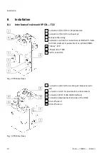
Page 10: ...r direct pressure measurement on cylinder DSBG 6 Status LED 7 Power Error LED 8 Earth connection Fig 2 VPCB interfaces 2 Connection 2 G3 8 for working air balancer cylin der 9 Connection G1 8 for pneu...

Page 11: ...ter 12 mm 2 Connect pressure gauge input connection 9 Bedienelement of valve unit VPCB with handle VAOH Tubing diameter 6 mm Tube length 0 5 m 10 m 3 Assemble the silencer not in scope of delivery as...

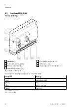
Page 12: ...O interfaces X2 X3 X4 X5 6 CAN interface X6 7 Power supply for the I O interfaces X5 Fig 4 Interfaces CECC D BA The status LEDs show the operating status of the CECC D BA Status LED Meaning Run Applic...

Page 13: ...mode X2 6 Reserved X2 7 Reserved X3 0 6 digital inputs System enable X3 1 X3 5 Can be configured by the user X4 0 8 digital outputs Operation enabled X4 1 Can be configured by the user X4 2 Shut off v...

Page 14: ...ava Script and support of HTML5 Canvas e g Firefox Chrome Internet Explorer Version 9 Screen resolution 1280 x 768 pixels 8 4 Electrical installation WARNING Risk of injury due to electric shock For t...

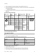
Page 15: ...4 WH CAN_H 1C 7 5 BU CAN_L 1C Manifold block BUS IN 2 24 V logic 2V 9 GND logic GND 3 2C Cable 2 wire 2C Manifold block BUS OUT 1 Colour code in accordance with IEC 60575 1983 01 Tab 5 Pin allocation...

Page 16: ...that serves as a reference sensor as follows SMT 8M A PS 24V OE CECC D BA Wire colour1 Function Connection BN 24 V DC supply 24 V load BK Switching output Digital input X2 3 BU GND 24 V GND 1 Colour c...

Page 17: ...sis must be carried out and all appropriate measures implemen ted Commissioning is dependent on the customer specific application During commissioning observe the associated documentation for the indi...

Page 18: ...unctions The display and elimination of malfunctions are dependent on the customer specific application During operation observe the associated documentation for the individual components installed 1...

Page 19: ...80 200 Travel speed m s 1 Operating voltage DC V 21 6 26 4 Duty cycle 100 Residual ripple 5 Operating pressure bar 4 8 Operating medium Compressed air to ISO 8573 1 2010 6 4 4 Lubricated operation no...

Page 20: ...ization is prohibited Offenders will be liable for damages All rights reserved in the event that a patent utility model or design patent is registered Copyright Festo AG Co KG 73734 Esslingen Ruiter S...

Reviews: