8.2
Pneumatic installation
•
Make pneumatic connections cable ends as short as possible.
•
Ensure sufficient torque for fittings and tightness of the pneumatic connections. A leakage can
lead to unwanted system behaviour.
For details on pneumatic installation, see circuit diagram
è
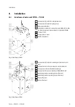
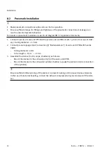
1. Connect input [1] of valve unit VPCB with a service unit and filter mesh 5 µm (not in scope of deliv-
ery). Tubing diameter:
³
12 mm
2. Connect pressure gauge input (connection [9] "Bedienelement") of valve unit VPCB with handle
VAOH.
–
Tubing diameter: 6 mm
–
Tube length:
³
0.5 m …
£
10 m.
3. Assemble the silencer (not in scope of delivery) as follows:
–
Mount the silencer to the exhaust ports [3] of the valve unit VPCB.
–
Mount the silencer to the exhausted cylinder chamber (usually the piston rod side connection
of the cylinder).
Ensure sufficient dimensioning of the silencer to prevent backlog and increased noise emissions.
In the case of ducted exhausting, connect the exhaust compressed air system instead of the silen-
cer.
Installation
12
Festo — YHBP-2 — 2018-11


