MS6-SV-...-D-10V24
16
Festo – MS6-SV-...-D-10V24 – 1702a English
6
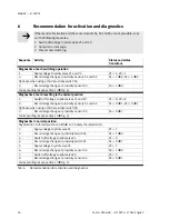
Recommendation for activation and diagnostics
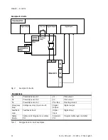
If the results of activation and the sensor signals S1, S2 and S3 are not plausible, carry
out the following measures:
1. Switch off voltage to pilot valves V1 and V2.
2. Output error message.
3. Prevent new switching.
Sequence
Activity
Status and status
transitions
Diagnostics at each switching operation
1.
Apply voltage to pilot valves V1 and V2.
V1 = 1; V2 = 1
2.
Record edge change at proximity sensors S1 and S2.
S1 = 1
è
0; S2 = 1
è
0
Optional, when using a third proximity switch S3:
3.
Record edge change at proximity sensor S3.
S3 = 1
è
0
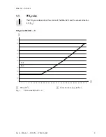
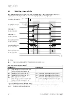
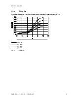
Corresponding response times (
è
Fig. 4).
Diagnostics at each resetting to the normal position
1.
Switch off voltage to pilot valves V1 and V2.
V1 = 0; V2 = 0
2.
Record edge change at proximity sensors S1 and S2.
S1 = 0
è
1; S2 = 0
è
1
Optional, when using a third proximity switch S3:
3.
Record edge change at proximity sensor S3.
S3 = 0
è
1
Corresponding response times (
è
Fig. 4).
Diagnostics in normal position
Pay attention to forced switch on/off (
è
15.1 Safety characteristics).
1.
Apply voltage to pilot valve V1
V1 = 1
2.
Record edge change at proximity switch S1.
S1 = 1
è
0
3.
Switch off voltage to pilot valve V1.
V1 = 0
4.
Record edge change at proximity switch S1.
S1 = 0
è
1
5.
Apply voltage to pilot valve V2.
V2 = 1
6.
Record edge change at proximity sensor S2.
S2 = 1
è
0
7.
Switch off voltage to pilot valve V2.
V2 = 0
8.
Record edge change at proximity sensor S2.
S2 = 0
è
1
Corresponding response times (
è
Fig. 4).
Tab. 6
Recommendation for activation and diagnostics


