background image

37

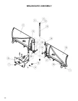
MOLDBOARD ASSEMBLY

Item  Part 

Qty Description

1.   07-0206        

Pin, Cotter, Gr2, 3/16 x 2 (5 ft)

    07-0206        

Pin, Cotter, Gr2, 3/16 x 2 (6,7,8,9,10 ft)

2.   07-0223        

Fitting, Zerk, 1/8NPT

3.   07-3268        

Snap Ring

4.   07-3674        

Screw, HHC, Gr8, 1/2-13 x 2 3/4

5.   07-4090        

Washer, 1 1/2  x 1 x .075 (5 ft)

    07-4090        

Washer, 1 1/2  x 1 x .075 (6,7,8,9,10 ft)

6.   07-6889        

Pin, Clevis, 1 x 5, 4.7 Grip (5 ft)

    07-6889        

Pin, Clevis, 1 x 5, 4.7 Grip (6,7,8,9,10 ft)

7.   07-7838        

Screw, HHC, Gr8, 1 1/2-6 x 6

8.   07-8083        

Nut, Gr8, 1 1/2-6

9.   07-8084        

Washer, Lock, Disk, 1 1/2

10. 13-17420        

Pivoting Assembly

11. 13-17426-60    

Weld, Left, Moldboard (5 ft)

    13-17426-72    

Weld, Left, Moldboard (6 ft)

    13-17426-84    

Weld, Left, Moldboard (7 ft)

    13-17426-96    

Weld, Left, Moldboard (8 ft)

    13-17426-108  

Weld, Left, Moldboard (9 ft)

    13-17426-120  

Weld, Left, Moldboard (10 ft)

12. 13-17430-60    

Weld, Right, Moldboard (5 ft)

    13-17430-72    

Weld, Right, Moldboard (6 ft)

    13-17430-84    

Weld, Right, Moldboard (7 ft)

    13-17430-96    

Weld, Right, Moldboard (8 ft)

    13-17430-108  

Weld, Right, Moldboard (9 ft)

    13-17430-120  

Weld, Right, Moldboard (10 ft)

13. 13-17442        

Shaft, 1.5 x 27.125

14. 13-17662        

Plate, 3/8 x 2 x 3.5, with Hole

15. LAF9602        

Spring Bushing/Bearing, 1.75 x 1/8 x 2

16. P158005        

Nut, Nylock, 1/2-13

17. P855324        

Bushing, Machine, 1-1/2 x 14ga

18. RHW5532       

Washer, Flat, 9/16, Gr5

19. RHW8222       

Pin, Clevis, 1 x 3 (5 ft) 

    RHW8222       

Pin, Clevis, 1 x 3 (6,7,8,9,10 ft) 

Summary of Contents for V-Snow Blade

Page 1: ...g com 2800 N Zeeb Rd Dexter MI 48130 United States of America Model Number_______________________ Serial Number___________________________ Manual Number 51 4320 Release Date December 2010 Serial Numbe...

Page 2: ...2 Notes...

Page 3: ...7 EQUIPMENT SAFETY PRECAUTIONS 8 SAFETY DECALS LABELS 9 INSTALLATION 10 OPERATION 11 19 MAINTENANCE SCHEDULE 20 MAINTENANCE RECORD 21 MAINTENANCE 22 23 TROUBLESHOOTING 24 28 PRODUCT SPECIFICATIONS 47...

Page 4: ...ned individuals that have read and understand this manual If there is any portion of this manual or function you do not understand contact your local authorized dealer or manufacturer to obtain furthe...

Page 5: ...LLOW ALL SAFETY INSTRUCTIONS IN THIS MANUAL AND THE PRIME MOVERS MANUAL WARNING READ AND UNDERSTAND ALL SAFETY STATEMENTS Read all safety decals and safety statements in all manuals prior to operating...

Page 6: ...ngs Keep unprotected body parts such as face eyes and arms as far away as possible from a suspected leak Flesh injected with hydraulic fluid may develop gangrene or other permanent disabilities If inj...

Page 7: ...me mover or this attachment Know your work site safety rules as well as traffic rules and flow When in doubt on any safety issue contact your supervisor or safety coordinator for an explanation EQUIPM...

Page 8: ...to prevent uncontrolled movement Drive slowly over rough ground and on slopes When driving on roads use safety lights reflectors Slow Moving Vehicle signs etc to prevent accidents Check local governme...

Page 9: ...ve and smooth out any bubbles Instructions 1 Keep all safety signs clean and legible 2 Replace all missing illegible or damaged safety signs 3 Replacement parts for parts with safety signs attached mu...

Page 10: ...ary hydraulic lines 8 Unfasten safety restraints and exit the prime mover 9 Ensure that the hydraulic quick couplers are clean Connect hydraulic lines for the blade to the prime mover Twist the collar...

Page 11: ...sengage the blade when it is in the V position 3 Lower the blade to the ground 4 Tilt the blade until the mounting is on the ground 5 Engage the parking brake and shut off the prime mover Relieve the...

Page 12: ...ic fittings are tight Replace any damaged or fatigued fittings or hoses Remove from the plowing area all property that could be damaged by flying debris or impacts from the blade Be sure all persons n...

Page 13: ...r The seat belt must be fastened while you operate the prime mover Only operate the controls while the engine is running Protective glasses must be worn while you operate the prime mover and while you...

Page 14: ...le still reversing flow retract left blade until it is in the straight position 3 Use normal flow to extend right blade until it is parallel to left blade V Position Reverse flow until both blades ret...

Page 15: ...en lower to the ground 3 Adjust blade until it is level to the ground refer to leveling instructions 4 Increase prime mover engine rpm to operating speed Angling Instructions 1 Press toggle switch and...

Page 16: ...ace and a gap is visible towards the outer sides of the attachment figure 3 1 Lift attachment 2 Roll attachment forward 3 Lower back to ground 4 Continue until level V Position If the front corner of...

Page 17: ...17 OPERATION figure 2 figure 3 Level Scoop Position Shown...

Page 18: ...in 108 in 120 in Recommended Spring Set up Length 14 38 inches Maximum Length Permitted 15 33 inches 6 Test snow blade If edges trip too easily perform the following steps a Repeat the above steps 1...

Page 19: ...prime mover on a firm level surface with blade properly attached 2 Lower the blades cutting edge onto a sturdy wood or metal blocking to safely hold the skid shoes 2 5 to 3 inches off the level surfac...

Page 20: ...sonal injury Check lines tubes and hoses carefully Do not use your hand to check for leaks Use a board or cardboard to check for leaks Tighten all connections to the recommended torque Do not bend hig...

Page 21: ...rods with grease Lubricate grease fittings Seal hydraulic system from contaminants and secure all hydraulic hoses off the ground to help prevent damage Store unit in a dry and protected place Leaving...

Page 22: ...y to prevent unintended disengagement Failure to do so could result in the attachment falling and causing serious personal injury or death TIE DOWN POINTS Tie down points are identified by tie down de...

Page 23: ...dware Check for tightness Oil Cleanliness Requirements NOTICE All hydraulic fluid shall be filtered before use in any FFC product to obtain the ISO cleanliness standard of 17 14 or better unless expli...

Page 24: ...24 MAINTENANCE RECORD Date Maintenance Procedure Performed Performed by Comments...

Page 25: ...h end of the wear edge 5 Support one end of the wear edge remove the nut and bolt then lower it to the level surface 6 Support the other end remove the nut and bolt and lower to the level surface 7 Fl...

Page 26: ...the level surface 6 Support the other end remove the nut and bolt and lower to the level surface 7 Discard used wear edge and all nuts and bolts 8 Support one end of the new wear edge and install wit...

Page 27: ...g brake 4 Remove and retain all nuts and bolts but the ones at each end of the wear edge 5 Support one end of the wear edge remove the nut and bolt then lower it to the level surface 6 Support the oth...

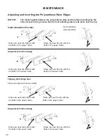
Page 28: ...e near the top with the bolts in the upper holes Holes are near the bottom with the bolts in the lower holes Holes are near the top with the bolts in the lower holes Note retaining plate positions Adj...

Page 29: ...ubber wear edge and nylon center edges NOTICE Use only 20 FT LBS of torque on button head bolts for nylon center edges Inverting the Center Nylon and Rubber Wear Edges 1 Remove hardware from rubber ce...

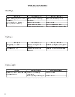
Page 30: ...r replace wear edge Center wear edge is worn Flip or replace center wear edge Trip Edges Problem Possible Cause Possible Solution Edges trip too easily Tension spring not set properly Refer to Spring...

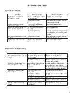
Page 31: ...t Hoses may be installed improperly Re install hoses correctly Problem Possible Cause Possible Solution Both cylinders do not extend nor retract Hoses or fittings are loose or disconnected Tighten hos...

Page 32: ...Seal 7 03 6244 4 Hose 38 x 24 6FF 6FF45 3K 8 03 6293 2 Fitting Elbow 45 8MB 8MF 9 07 4032 6 Washer Flat Gr8 1 4 10 07 4033 2 Nut Hex nylock 1 4 20 Gr8 11 07 7737 1 Wire Harness 108 inches 12 19687 1...

Page 33: ...03 4704 2 Hose 38 x 27 6FF 6FF 3K 6 03 5236 2 Hose 38 x 42 6FF 6FF90 3K 7 03 5903 1 Manifold 8 03 6248 2 Plate Hydraulic Orifice 6 ORFS 9 07 3652 2 Screw HHC Gr8 5 16 18 x 3 1 2 10 88921 2 Cylinder As...

Page 34: ...34 HYDRAULIC ELECTRIC MANIFOLD SCHEMATIC...

Page 35: ...35 HYDRAULIC MANIFOLD SCHEMATIC...

Page 36: ...36 MOLDBOARD ASSEMBLY...

Page 37: ...Moldboard 5 ft 13 17426 72 1 Weld Left Moldboard 6 ft 13 17426 84 1 Weld Left Moldboard 7 ft 13 17426 96 1 Weld Left Moldboard 8 ft 13 17426 108 1 Weld Left Moldboard 9 ft 13 17426 120 1 Weld Left Mo...

Page 38: ...17406 120 1 Weld Left Trip Edge 10 ft 3 13 51846 2 Weld Trip Spring Arm 4 RHW7607 4 Nut Flange Top Lock 63 11 Gr8 5 RHW8065 4 Bolt Spade 62 x 3 25 6 RHW8222 4 Pin Clevis 1 x 3 7 07 4090 4 Washer 1 1 2...

Page 39: ...Edge 6 x 5 5 ft 13 17412 72 2 Wear Edge 6 x 5 6 ft 13 17412 84 2 Wear Edge 6 x 5 7 ft 13 17412 96 2 Wear Edge 6 x 5 8 ft 13 17412 108 2 Wear Edge 6 x 5 9 ft 13 17412 120 2 Wear Edge 6 x 5 10 ft 4 07 7...

Page 40: ...40 OPTIONAL MARKER KIT Item Part Qty Description 1 103006 2 Marker Orange 28 inches 2 RHW1105 4 Screw HHC Gr5 31 18 x 1 3 RHW7103 4 Nut Lock Gr5 31 18...

Page 41: ...41 NOTES...
Page 42: ...42 Specifications and Model Views PRODUCT SPECIFICATIONS V Position Straight Position Scoop Position Angle Position...

Page 43: ...imum Length Straight Position 38 inches 38 inches 38 inches 38 inches 38 inches 38 inches Maximum Width Scoop Position 54 inches 65 inches 75 inches 85 inches 95 inches 106 inches Plowing Width Scoop...

Page 44: ...istance to vibrating loose is required and greater operating temperatures are not a factor In addition like lock nuts nylock nuts have a safety feature that if the bolt does vibrate loose the nut will...

Page 45: ...clean hydraulic oil 4 Position tube and nut squarely on face seal of fitting and tighten nut finger tight 5 Using appropriate torquing device tighten to given torque rating from the table below Torque...

Page 46: ...ible and push washer up as far as possible figure 4 5 5 Screw fitting into port Hand tighten fitting until backup washer contacts face of port figure 6 6 To position the fitting unscrew to desired pos...

Page 47: ...the option to repair or replace the product b Timely Repair and Notice In order to obtain the Limited Warranty i the product must be repaired within thirty 30 days from the date of failure and ii a cl...

Reviews: