background image

Explosionproof Vibration Switch

Type 3171 Ex

Installation and Operating

Manual

EN

1. Introduction

The type 3171 Ex is a low-cost, vibration-sensitive, safety switch for the protection of rotating

and reciprocating machinery in hazardous environments. It is adjusted to operate above the

machine's normal running levels of vibration, activating machine shut-down circuits and/or

alarms and to switch off the machine before catastrophic failure.

The switch detects vibration in all directions. Unbalanced forces created by failing machinery

contain both the fundamental frequency and harmonics. The switch responds by shutting off the

machine if any components of vibration exceed the set value.

The switch operates as follows:

• Mounted vertically on a vibrating machine, a steel ball is held by a permanent magnet into

a conical seat

• If the vibration of the machine is sufficient to cause the ball to detach from the magnetic

field of the magnet, it trips a latched lever, thus releasing a micro switch plunger so the

machine can be stopped

• The ball and lever are latched by pressing the reset button manually

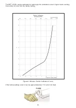
• The SET LEVEL of the vibration switch is set by adjusting the gap between permanent

magnet and ball.

Consult the FFE website at www.ffeuk.com for the latest information on applications and any

new warnings that may affect installation or safety.

1

Summary of Contents for 3171 Ex

Page 1: ...and harmonics The switch responds by shutting off the machine if any components of vibration exceed the set value The switch operates as follows Mounted vertically on a vibrating machine a steel ball...

Page 2: ...the field and not wired Unless the switch is immediately wired using a suitable cable gland replace the Cable Entry Cap with Blanking Plug 0051 002 01 see accessories For Ex compliance ensure a minimu...

Page 3: ...ch is factory set to 3 g unless a preset switch has been ordered To reduce the risk of damaging internal components and wiring installation and wiring must be performed within a temperature range of 1...

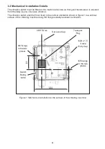
Page 4: ...itch shall be firmly fixed in the vertical orientation shown in figure 1 to a vertical surface of the vibrating machine using M5 fixings suitably resistant to vibration Figure 1 Mechanical installatio...

Page 5: ...at failure of the strain relief will cause the Earth wire to be the last conductor interrupted To prevent water running down onto the vibration switch add a drip loop in any external cabling For ambie...

Page 6: ...ess multiple conductors have been joined in a suitable manner e g by a single insulated crimped bootlace ferrule Wiring to terminals shall be insulated for the appropriate voltage and this insulaton s...

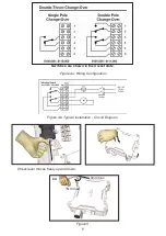
Page 7: ...7 Figure 4a Wiring Configuration Switches are shown in their reset state x4 3mm hex 1Nm max Check lever moves freely up and down Figure 5 Figure 4b Typical Installation Circuit Diagram...

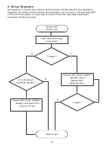
Page 8: ...N N Advance SET LEVEL SCREW steadily 1 2 turn Reset switch Reset Machine 5 Set up Sequence No adjustment is needed if the vibration switch has been ordered preset for your application Otherwise the vi...

Page 9: ...referring to the calibration curve in figure 6 and counting the number of turns from the factory setting If the factory setting is lost it can be approximated as 11 5 turns from flush Figure 6 Vibrat...

Page 10: ...s not required except for periodic external visual inspection of the following Confirm lid screws and vibration switch M5 fixings to machine are tight Confirm cable gland is tight to the enclosure and...

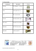
Page 11: ...Picture 1000 026 LID ASSEMBLY TYPE MR G003 GLAND M20 TRS C I P S171 SEAL 400 024449041 1000 027 4MM HEX DRIVER LONG 0051 002 01 BLANKING PLUG IP66 67 23640 083 ADAPTOR 20mm MALE 23640 085 CABLE GLAND...

Reviews: