ALINTE
4
PAGE
I
NSTALLATION
G
UIDE
4-45
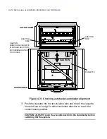
NOTE: Unlatch the cassette from the autoloader by pulling back
the latch arm under the cassette base.
4.
If there is slight movement then:
raise the autofeeder feet
move the autofeeder slightly in the
same
‘nudge’ direction to
re-align with the location pins
lower the feet on the autofeeder.
5.
Repeat the steps above to check the alignment again until the
cassette latches correctly.
6.
Tighten the 4-off screws on adaptor angles and the 4-off screws on
the adaptor top.
7.
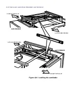
Check the level between the two units, see
Figure 4.25 on page 4-33
.
8.
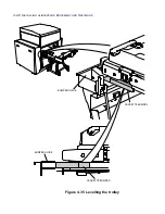
Once the two modules are level, secure the two units together with 4-
off M5 x 20 cap head screws supplied in the Support Pack, see
Figure 4.34 on page 4-46
.
Summary of Contents for alinte4page
Page 1: ......
Page 12: ...PRELIMINARIES...
Page 29: ...ALINTE4PAGE INSTALLATION GUIDE 2 7 Figure 2 5 Autofeeder elevator warning label...
Page 40: ...2 18 SAFETY ON THE ALINTE4PAGE Figure 2 13 Location of interlock covers alinte4page SAL 2 1...
Page 48: ...2 26 SAFETY ON THE ALINTE4PAGE...
Page 56: ...3 8 UNPACKING AND HANDLING...
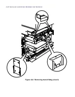
Page 98: ...4 42 INSTALLING ALINTE4PAGE EQUIPMENT AND SOFTWARE Figure 4 32 Removing transit fixing view 2...

