ALINTE
4
PAGE
I
NSTALLATION
G
UIDE
4-49
4.6 Set up the System
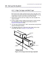
4.6.1 Align Carriage and Ball Cage
Both the traverse carriage and ball cage are setup manually so that
they always move back and forward as aligned assemblies. The pro-
cedure below is carried out at the user end of the Engine.
1.
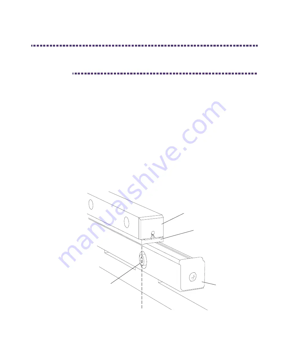
Hold the ball cage and push the carriage back until a length of the
cage is exposed.
2.
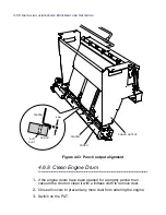
Pull the carriage forward, holding the ball cage as required until the
two assemblies are inline with the screw fixing as shown in
Figure 4.36 on page 4-49
below.
3.
You may have to repeat steps
1.
and
2.
several times to align the ball
cage and carriage accurately.
4.
The alignment and level is checked at a later stage using a cage
creep utility described in
Section 5.2.4 on Page 5-5
.
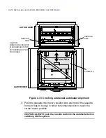
Figure 4.36 Carriage rail and ball cage alignment
ALIGN BALL CAGE AND
CARRIAGE RAIL HERE
CARRIAGE
RAIL
BALL
CAGE
USER
END
VIEW
FIRST
SCREW
V-GROOVE
Summary of Contents for alinte4page
Page 1: ......
Page 12: ...PRELIMINARIES...
Page 29: ...ALINTE4PAGE INSTALLATION GUIDE 2 7 Figure 2 5 Autofeeder elevator warning label...
Page 40: ...2 18 SAFETY ON THE ALINTE4PAGE Figure 2 13 Location of interlock covers alinte4page SAL 2 1...
Page 48: ...2 26 SAFETY ON THE ALINTE4PAGE...
Page 56: ...3 8 UNPACKING AND HANDLING...
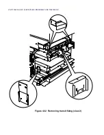
Page 98: ...4 42 INSTALLING ALINTE4PAGE EQUIPMENT AND SOFTWARE Figure 4 32 Removing transit fixing view 2...


