ALINTE
4
PAGE
I
NSTALLATION
G
UIDE
5-25
6.
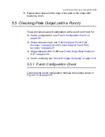
Repeat these steps until the edge of the plate to the image start
position is
2
mm.
5.5 Checking Plate Output (with a Punch)
These procedures apply to platesetters
with
a punch and check for:
Punch configuration
: see
“Punch Configuration Check” on
page 5-25
.
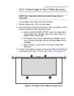
Image skew accuracy
: see
“Check Image to Punch Crop
Accuracy” on page 5-28
and
“Check Image to Top of Plate
Accuracy” on page 5-27
.
Image base position in RIP
: see
“Check Image Base Position in
RIP” on page 5-29
.
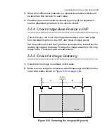
Punch centering
: see
“Check for Image Centering” on page 5-29
.
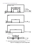
5.5.1 Punch Configuration Check
Check that the punch configuration matches the example shown in
Figure 5.15 on page 5-26
.
Summary of Contents for alinte4page
Page 1: ......
Page 12: ...PRELIMINARIES...
Page 29: ...ALINTE4PAGE INSTALLATION GUIDE 2 7 Figure 2 5 Autofeeder elevator warning label...
Page 40: ...2 18 SAFETY ON THE ALINTE4PAGE Figure 2 13 Location of interlock covers alinte4page SAL 2 1...
Page 48: ...2 26 SAFETY ON THE ALINTE4PAGE...
Page 56: ...3 8 UNPACKING AND HANDLING...
Page 98: ...4 42 INSTALLING ALINTE4PAGE EQUIPMENT AND SOFTWARE Figure 4 32 Removing transit fixing view 2...


