ALINTE
4
PAGE
I
NSTALLATION
G
UIDE
3-5
8.
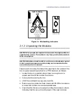
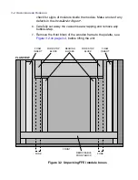
Remove any foam inserts around the palette.
9.
Use the fork-lift truck to remove the module from the palette, see
also Section (CrossRefFormat> “Using a Fork-Lift” on
page 3-7
. A
limit block at the rear of the plinth locates the position of each fork
before the unit is raised.
CAUTION: Check that the anchor feet are fully retracted.
10.
Once the module is removed from its palette, carefully push or lift
it to its working location.
If you need to use a harness and slings for raising the module,
refer to FFEI Customer Support (UK).
11.
Locate the Accessories packs and check that the items in
Table 3.1 on page 3-5
are shipped.
12.
Arrange locally for the removal of disposable packaging materials.
The box cardboard and foam are all recyclable materials.
Table 3.1 alinte4page accessories packs
1
FireWire cable (10 m)
2
User’s Safety Guide
3
Getting Started Guide
4
Manifold blanking plate and (4-off M6 screws)
5
alinte4page CTP (Application) CD
6
alinte4page CTP (PCI) CD
7
Celebrant alinte4page patch CD (requires software dongle
key), if required.
8
Diagnostics comms cable (10 m or optional 25 m)
9
Vacuum pump (VT4.25)
10
Output buffer to processor (10-off M6 screws) (Semi-auto
only)
11
Vacuum Nylon tube 16 mm black
12
G10 film sheet for PC next to a manual loading machine
13
alinte4page CTP Product Manuals CD
Summary of Contents for alinte4page
Page 1: ......
Page 12: ...PRELIMINARIES...
Page 29: ...ALINTE4PAGE INSTALLATION GUIDE 2 7 Figure 2 5 Autofeeder elevator warning label...
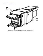
Page 40: ...2 18 SAFETY ON THE ALINTE4PAGE Figure 2 13 Location of interlock covers alinte4page SAL 2 1...
Page 48: ...2 26 SAFETY ON THE ALINTE4PAGE...
Page 56: ...3 8 UNPACKING AND HANDLING...
Page 98: ...4 42 INSTALLING ALINTE4PAGE EQUIPMENT AND SOFTWARE Figure 4 32 Removing transit fixing view 2...


