ALINTE
4
PAGE
I
NSTALLATION
G
UIDE
4-9
4.1.5.4 Alinte4page MAL
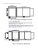
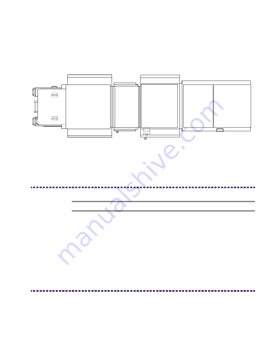
Install a multi-cassette system in the the following module order
Figure 4.8 on page 4-9
.
Figure 4.8 Install sequence: alinte4page MAL
4.2 Install the Processor
CAUTION: Lifting this unit is a five-man operation.
Using the supplied Installation Manual, install the processor and its
chiller unit.
1.
Locate the processor in its correct working position.
2.
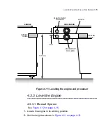
Set the processor plate entry slot height to
1,012 mm
(
39.84 in
)
to
match the output of the Engine, see
Figure 4.11 on page 4-15
.
3.
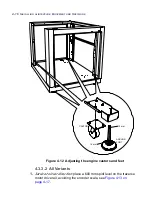
Level the processor at each corner.
4.3 Install the Engine
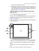
4.3.1 Remove Engine Transit Fixings
The Engine is shipped with a set of transit fixings that MUST be
removed BEFORE switching on power. Each fixing is identified by a
label colour-coded
orange
; all screw fixings are colour-coded
green
.
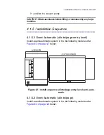
(1) PROCESSOR
(2) ENGINE
(3) AUTOLOADER
(5) TROLLEY &
CASSETTE
(4) AUTOFEEDER
Summary of Contents for alinte4page
Page 1: ......
Page 12: ...PRELIMINARIES...
Page 29: ...ALINTE4PAGE INSTALLATION GUIDE 2 7 Figure 2 5 Autofeeder elevator warning label...
Page 40: ...2 18 SAFETY ON THE ALINTE4PAGE Figure 2 13 Location of interlock covers alinte4page SAL 2 1...
Page 48: ...2 26 SAFETY ON THE ALINTE4PAGE...
Page 56: ...3 8 UNPACKING AND HANDLING...
Page 98: ...4 42 INSTALLING ALINTE4PAGE EQUIPMENT AND SOFTWARE Figure 4 32 Removing transit fixing view 2...

