ALINTE
4
PAGE
I
NSTALLATION
G
UIDE
4-13
4.3.2 Integrate the Processor and Engine
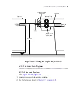
4.3.2.1 Set the Processor Height
Using the supplied OEM Installation Manual, install the processor and
its chiller unit.
See
Figure 4.11 on page 4-15
.
1.
Locate the processor in its correct working position.
2.
Remove the processor top cover and heater cover.
3.
Slide a solid 6-inch steel rule (or straight edge) between the rubber
nip rollers and the plastic input rollers until it is sticking out the front
guide in the centre. It should be level with the heater plate.
4.
Using the appropriate 12 mm and 16 mm spanners, adjust the feet so
that the bottom of the rule is
1,012 mm
from the floor.
Make sure the input rollers and tank frame are level in both planes.
NOTE: Do not use the engine panels for levelling.
5.
Re-adjust the feet if necessary while maintaining the correct height at
the centre.
6.
Remove the rule.
4.3.2.2 Mate the Engine to the Processor
See
Figure 4.11 on page 4-15
.
1.
Fit the processor input plate (buffer) with the screws supplied in the
Accessory Pack.
2.
Position the engine frame against the processor buffer frame.
3.
Adjust the engine feet until both frames are roughly at the same
height.
4.
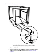
Level the engine drum/beam/optics cover assemblies in both planes
using a spirit level. See
Figure 4.13 on page 4-17
.
5.
Place the steel rule against the top surface of the output guide and
slide the guide into the processor and over the small plastic input
rollers.
Summary of Contents for alinte4page
Page 1: ......
Page 12: ...PRELIMINARIES...
Page 29: ...ALINTE4PAGE INSTALLATION GUIDE 2 7 Figure 2 5 Autofeeder elevator warning label...
Page 40: ...2 18 SAFETY ON THE ALINTE4PAGE Figure 2 13 Location of interlock covers alinte4page SAL 2 1...
Page 48: ...2 26 SAFETY ON THE ALINTE4PAGE...
Page 56: ...3 8 UNPACKING AND HANDLING...
Page 98: ...4 42 INSTALLING ALINTE4PAGE EQUIPMENT AND SOFTWARE Figure 4 32 Removing transit fixing view 2...

