ALINTE
4
PAGE
I
NSTALLATION
G
UIDE
4-17
Ensure that the horizontal level between the two ends is less than
0.5
mm.
2.
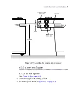
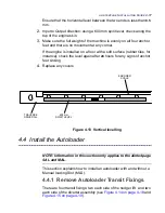
Input to Output direction: using a 600 mm spirit level, check along the
top of the engine skin.
3.
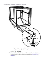
Make sure the full weight of the machine is evenly on all four anchor
feet and there is no movement at any corner.
If the engine is installed on a floor with a soft surface (rubber tiles, for
instance), check the level again after
24
hours for any signs of anchor
feet sinking.
4.
Replace any covers.
Figure 4.13 Vertical levelling
4.4 Install the Autoloader
NOTE: Information in this section only applies to the alinte4page
SAL and MAL.
This section explains how to install an autoloader with and without a
Manual loading Slot (MLS).
4.4.1 Remove Autoloader Transit Fixings
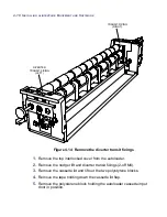
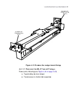
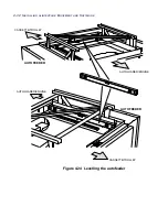
There are four transit fixings: two each side of the nudger lift and two
each side of the diverter assembly (see
Figure 4.14 on page 4-18
and
Figure 4.15 on page 4-19
).
ENCODER
SCALE
TRAVERSE
DRIVE RAIL
600 mm
SPIRIT LEVEL
Summary of Contents for alinte4page
Page 1: ......
Page 12: ...PRELIMINARIES...
Page 29: ...ALINTE4PAGE INSTALLATION GUIDE 2 7 Figure 2 5 Autofeeder elevator warning label...
Page 40: ...2 18 SAFETY ON THE ALINTE4PAGE Figure 2 13 Location of interlock covers alinte4page SAL 2 1...
Page 48: ...2 26 SAFETY ON THE ALINTE4PAGE...
Page 56: ...3 8 UNPACKING AND HANDLING...
Page 98: ...4 42 INSTALLING ALINTE4PAGE EQUIPMENT AND SOFTWARE Figure 4 32 Removing transit fixing view 2...


